Blade structure for a gas turbine engine

a gas turbine engine and blade structure technology, applied in the direction of motors, climate sustainability, air transportation, etc., can solve the problems of static flexural torque in the blades, dynamic flexural torque, and dynamic flexural torqu

Inactive Publication Date: 2002-11-12
MTU AERO ENGINES GMBH
View PDF13 Cites 91 Cited by
  • Summary
  • Abstract
  • Description
  • Claims
  • Application Information

AI Technical Summary

Problems solved by technology

Additionally, dynamic flexural torque arises due to blade vibration.
As mentioned, when a fabricated guide vane ring is used in a gas turbine, static flexural torque arises ...

Method used


Image

  • Blade structure for a gas turbine engine
  • Blade structure for a gas turbine engine
  • Blade structure for a gas turbine engine

Examples


Embodiment Construction

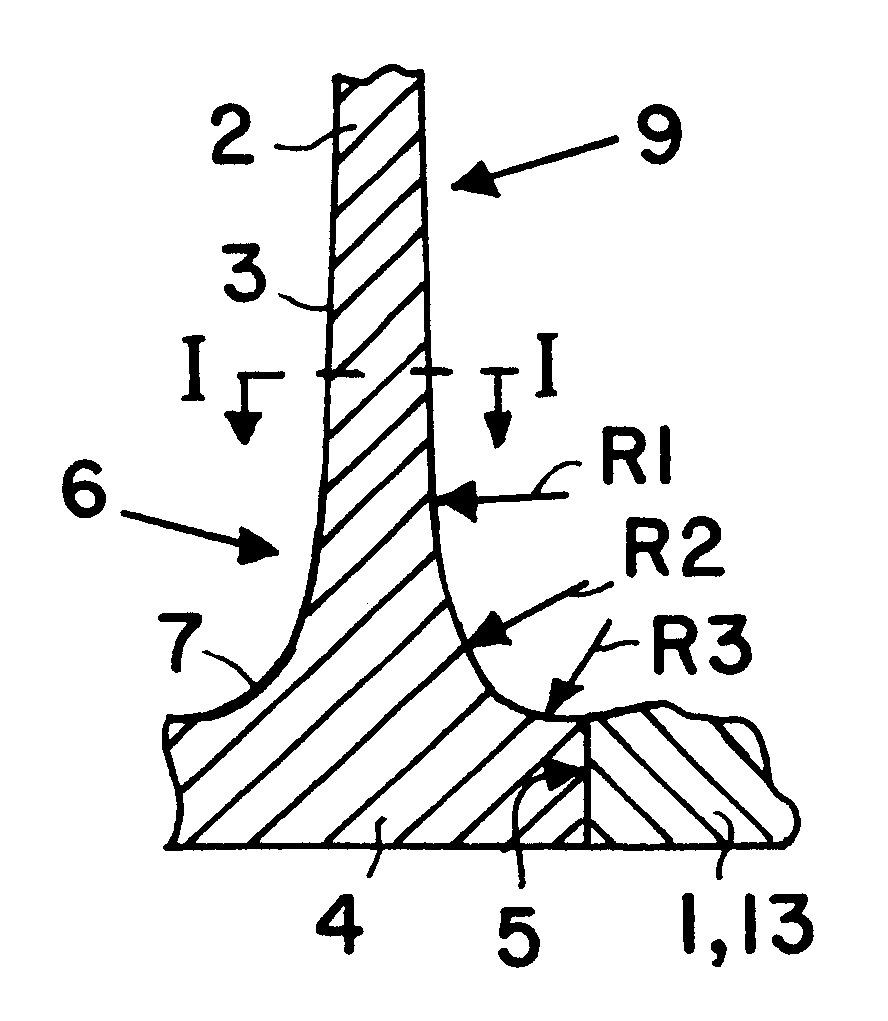
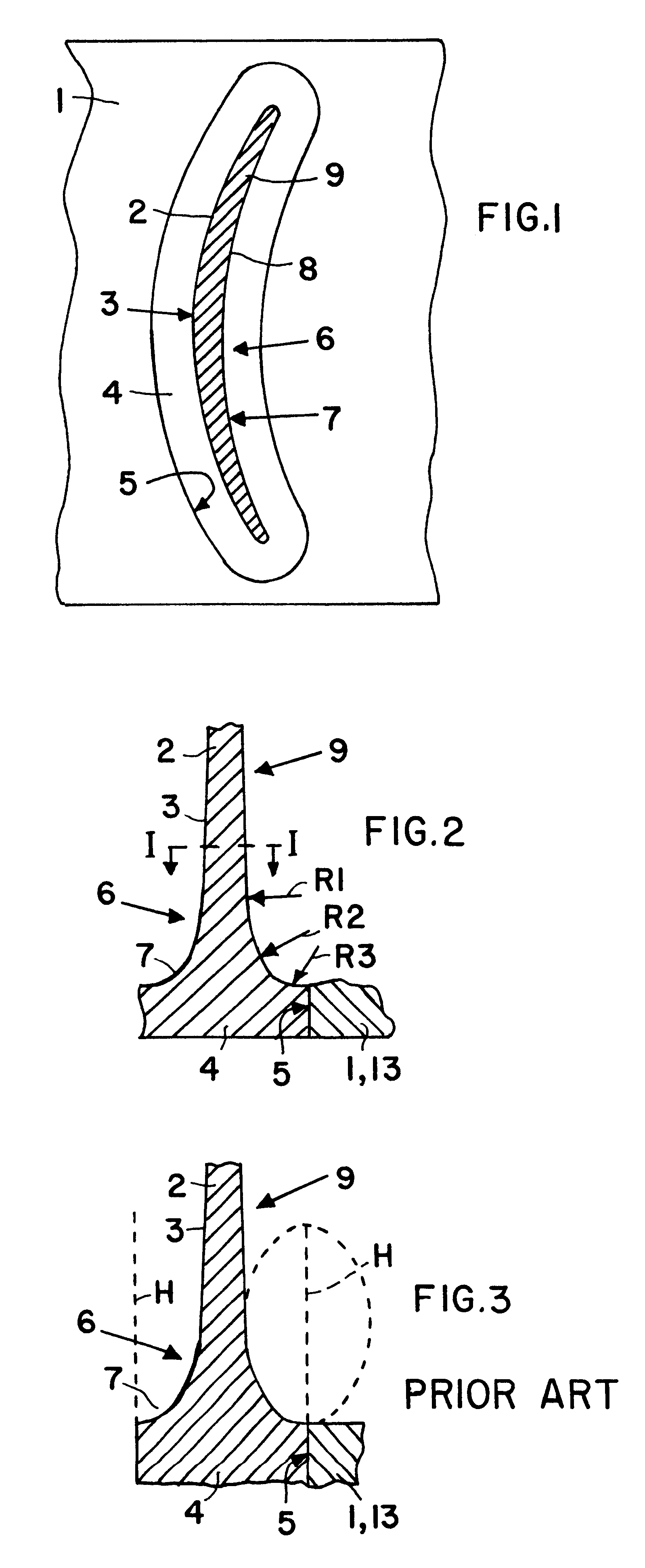
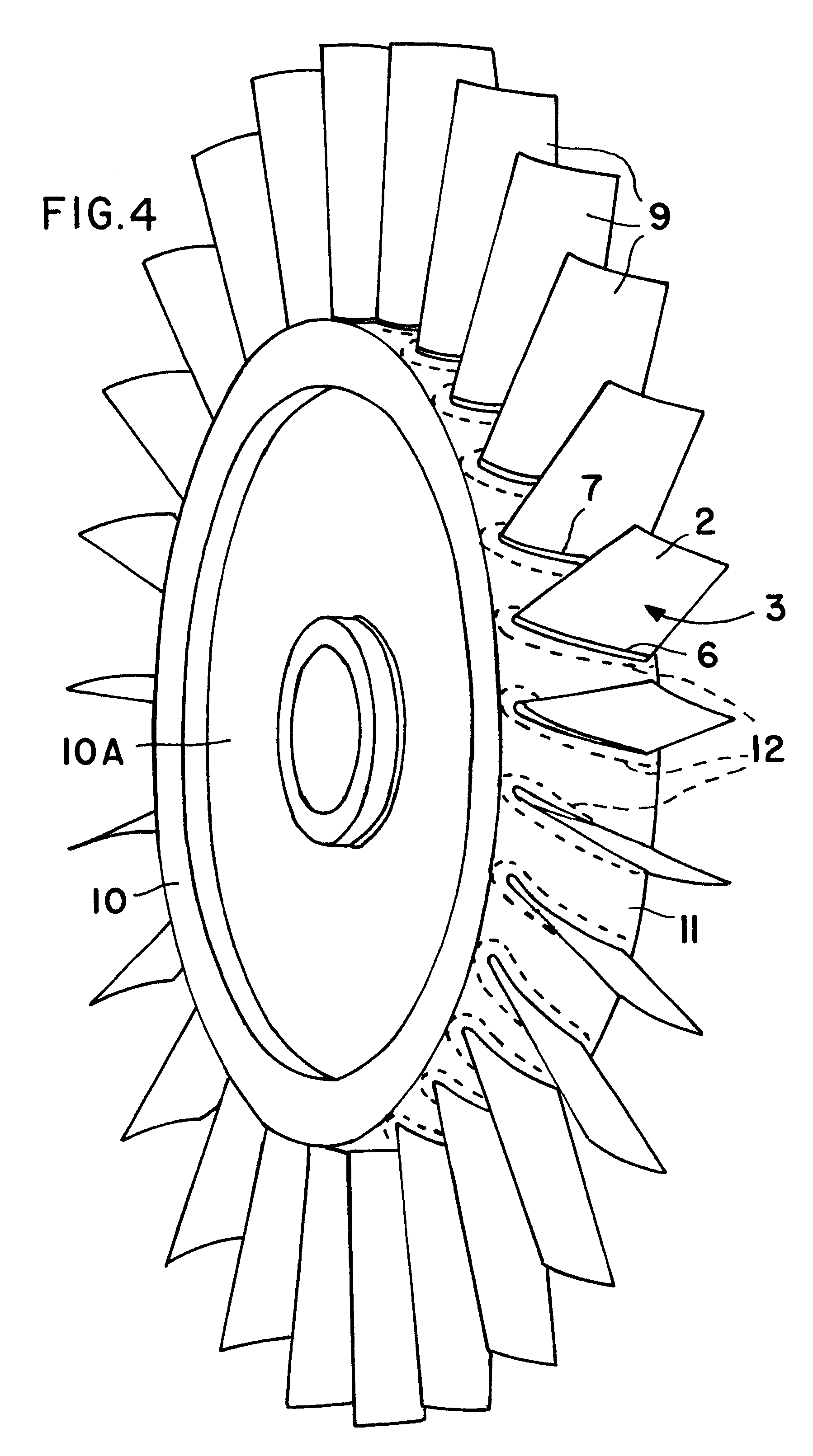
FIG. 1 shows a view in the radially inward direction and partly in section along section line I--I in FIG. 2 of an example embodiment illustrating a portion of a stator guide or carrier ring forming a shroud 1 and a portion of a flow guide blade 9 forming an airfoil 2 with a convex surface 3, a concave surface 8 and a blade foot. The blade foot of the guide blade 9 forms a platform 4 so that the platform is part of the blade rather than of the carrier ring. In the outer surface of the shroud 1 there are several generally equidistant recesses or holes 5 in which the blade platform 4 is inserted and attached in the recess, e.g. by soldering or welding or brazing. To reduce the resulting mechanical stress from flexural torque due to the force of the gas or due to vibrations, a transition or fillet 6 between the airfoil 2 and the platform 4, or rather the platform surface facing the airfoil 2, is formed as a fillet 6 having a curvature 7 that narrows toward the platform 4. This surface ...


PUM


Abstract

A blade ring for a gas turbine engine, especially an aircraft engine, may be a rotor ring or disk or a stator ring. At least one blade (9) forming an airfoil (2) is secured to at least one carrier ring (1, 10). The blade (9) is fixed to the carrier ring or disk or shroud (1, 10), either through a platform (4) forming a foot portion of the blade or through a neighboring transitional section (12) forming part of the carrier ring or disk or shroud. The mechanical stress and the overall axial length of the blade ring are reduced by a transition fillet (6) between the surfaces (3) of the airfoil (2) and the platform (4) or the peripheral section (12). The transition fillet (6) has a curve (7) that narrows toward the platform (4) or peripheral section (12) with radii (R1, R2, R3) that have different centers and are largest close to the blade surface (3, 8) and smallest close to the ring surface. This fillet construction extends all around the blade and relative to an inner ring or disk and/or an outer ring.

Description

The invention relates to a blade ring or blade structure for a gas turbine engine, especially an aircraft engine. A ring or disk forms a carrier for at least one blade, that forms an airfoil with its surface and is fixed to the carrier.BACKGROUND INFORMATIONBlade rings for gas turbine engines usually comprise a carrier such as a disk, or ring, or a housing part, or a shroud to which normally several blades are attached in corresponding holes in the carrier.When rotor blade rings of fabricated rotors are used in a gas turbine, static flexural torque arises in the blades due to centrifugal forces and due to the force of the gas. Additionally, dynamic flexural torque arises due to blade vibration. To avoid damage, it is important to reduce the resulting mechanical stress at the transition from the blade to the carrier. This stress reduction is also important for rotors with integral blades at the transition of the respective blade to the peripheral surface of the carrier.Fabricated gui...

Claims


Application Information

Patent Timeline
IPC IPC(8): F01D5/14
CPCF01D5/143Y02T50/671Y02T50/673Y02T50/60
Inventor TRUTSCHEL, RALF
Owner MTU AERO ENGINES GMBH
Why Eureka
Try Eureka