Heart occlusion devices

Active Publication Date: 2009-09-10
WL GORE & ASSOC INC
View PDF18 Cites 91 Cited by
  • Summary
  • Abstract
  • Description
  • Claims
  • Application Information

AI Technical Summary

Benefits of technology

[0035]Security: There will be the opportunity to remain tethered to the implanted device before releasing it, which is an extra security feature.
[0036]The device of the present invention should be appropriate for an ASD (atrial septal defect), PFO (patent foramen ovale), VSD (ventricular septal defect), and PDA (patent ductus arteriosus) with minor modifications.
[0037]An important use of the device will also be in closure of an aperture in a left atrial appendage. The device can be modified to conform to the atrial appendage anatomy. The discs are modified so that the device is not extruded out with the heart

Problems solved by technology

While there is currently no definitive proof of a cause-effect relationship, many studies have confirmed a strong association between the presence of a PFO defect and the risk for paradoxical embolism or stroke.
In addition, there is significant evidence that patients with a PFO defect who have had a cerebral vascular event are at increased risk for future, recurrent cerebrovascular events.
These patients are commonly treated with oral anticoagulants, which potentially have adverse side effects, such as hemorrhaging, hematoma, and interactions with a variety of other drugs.
However, umbrella devices and the like that are designed for ASDs are not optimally suited for use as PFO closure devices.
Currently available septal closure devices present drawbacks, including technically complex implantation procedures.
Many devices have high septal profile and include large masses of foreign material, which may lead to unfavorable body adaptation of a device.
Given that ASD devices are designed to occlude holes, many lack anatomic conformability to the flap-like anatomy of PFOs.
Hence, a device with a waist which can conform to the defect will have much higher chance of completely closing the defect.
Even if an occlus

Method used


Image

  • Heart occlusion devices
  • Heart occlusion devices
  • Heart occlusion devices

Examples


Embodiment Construction

[0056]The present invention provides a device for occluding an aperture within body tissue. One skilled in the art will recognize that the device and methods of the present invention may be used to treat other anatomical conditions in addition to those specifically discussed herein. As such, the invention should not be considered limited in applicability to any particular anatomical condition.

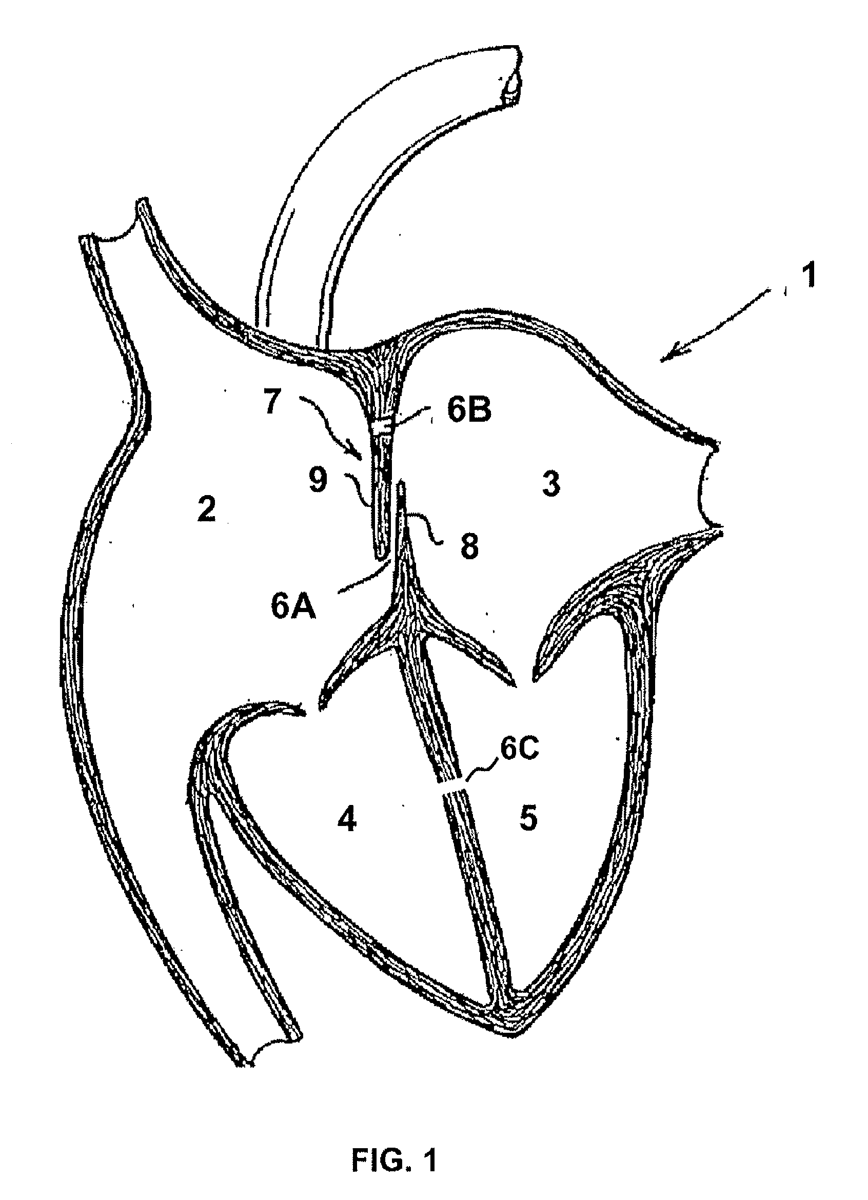
[0057]FIG. 1 illustrates a human heart 1, having a right atrium 2, a left atrium 3, a right ventricle 4, and a left ventricle 5. Shown are various anatomical anomalies 6A, 6B, and 6C. The atrial septum 7 includes septum primum 8 and septum secundum 9. The anatomy of the septum 7 varies widely within the population. In some people, the septum primum 8 extends to and overlaps with the septum secundum 9. The septum primum 8 may be quite thin. When a PFO is present, blood could travel through the passage 6A between septum primum 8 and septum secundum 9 (referred to as “the PFO tunnel”). Additionall...


PUM


Abstract

The present invention is specifically directed to a heart occlusion device with a self-centering mechanism. The heart occlusion device includes two separate uniquely shaped wires 12, 14, each forming shapes that mirror the respective wire's shapes. Each wire forms half-discs or quarter-discs that together form a distal disc and a proximal disc. In other versions, the device includes four separate wires, each mirroring its neighboring wire and forming a proximal and a distal quarter-disc. In the versions with four wires, the quarter-discs of each wire together form proximal and distal discs. The distal disc and proximal disc are separated by a self-centering waist. The proximal disc is attached to a hub comprising a screw mechanism. A similar hub is optional on the distal disc. The discs further include coverings which form a sealant to occlude an aperture in a tissue. The wires forming the discs have a shape-memory capability such that they can be collapsed and distorted in a catheter during delivery but resume and maintain their intended shape after delivery.

Description

REFERENCE TO RELATED APPLICATION[0001]The application claims priority to U.S. Provisional Application entitled “HEART OCCLUSION PLUG,” Ser. No. 61 / 034,772, filed Mar. 7, 2008, which is incorporated herein by reference in its entirety.FIELD OF THE INVENTION[0002]The present invention is directed to a medical device and particularly to a device for closing congenital cardiac defects. The present invention is specifically directed to a heart occlusion device with a self-centering mechanism.DESCRIPTION OF THE PRIOR ART[0003]Heart occlusion devices for correcting congenital heart defects, such as atrial septal defects (“ASD”), patent foramen ovale (“PFO”) defects, ventricular septal defects (“VSD”), and patent ductus arteriosus (“PDA”) defects, are known to the medical field. The following companies manufacture different types of devices: AGA Medical, Microvena Corp. / EV3 Medical, Velocimed / St. Jude Medical, Occlutech International, NMT Medical, Cardia, Inc., Solysafe S A, Sideris (Custom...

Claims


Application Information

Patent Timeline
IPC IPC(8): A61B17/08
CPCA61B2017/00597A61B2017/00623A61B17/12022A61B2017/00575A61B17/12145A61B2017/00632A61B17/12172A61B2017/12095A61B2017/00557A61B17/12122A61B2017/00243A61B2017/00867A61B17/0057A61B2017/00592A61B2017/00606A61B17/1214
Inventor AMIN, ZAHID
Owner WL GORE & ASSOC INC
Why Eureka
Try Eureka