Floor scrubber

a floor scrubber and scrubber technology, applied in the field of floor scrubbers, can solve the problems of reducing the useful life of the brush, increasing the wear of the bristle, and affecting the operation of the vacuum system, so as to avoid the problem of excess water application, reduce the total amount of liquid collected by the vacuum system, and operate longer

Inactive Publication Date: 2005-01-18
MINUTEMAN INT
View PDF7 Cites 87 Cited by
  • Summary
  • Abstract
  • Description
  • Claims
  • Application Information

AI Technical Summary

Benefits of technology

The forward water source includes spray nozzles directed downwardly onto the forward cylindrical scrub brush. The nozzles are fed by a constant displacement pump, and provide a uniform, measured dispersion of water across the entire cylindrical brush. By metering the water and dispensing the water uniformly across the entire cylindrical brush, the problem of excess water application is avoided. By reducing the amount of water for the cylindrical scrub brush, and by eliminating a ...

Problems solved by technology

One of the problems with a rider scrubber is that the suction recovery system can become plugged with loose or wet debris removed from the floor.
In an application which is solely sweeping, it was typically the practice not to apply a downward force on the cylindrical brush because it increases bristle wear and reduces the useful life of the brush.
Other problems with existing scrubbing systems using two counter-rotating cylindrical brushes with drip-type water dispersion include a lack of uniform application of water to the forward brush.
In order to provide a sufficient amount of water to all areas of the brush, some areas have excess water, resulting in an accumulation of excess water between the two brushes.
The excess water accumulation is du...

Method used


Image

  • Floor scrubber
  • Floor scrubber
  • Floor scrubber

Examples


Embodiment Construction

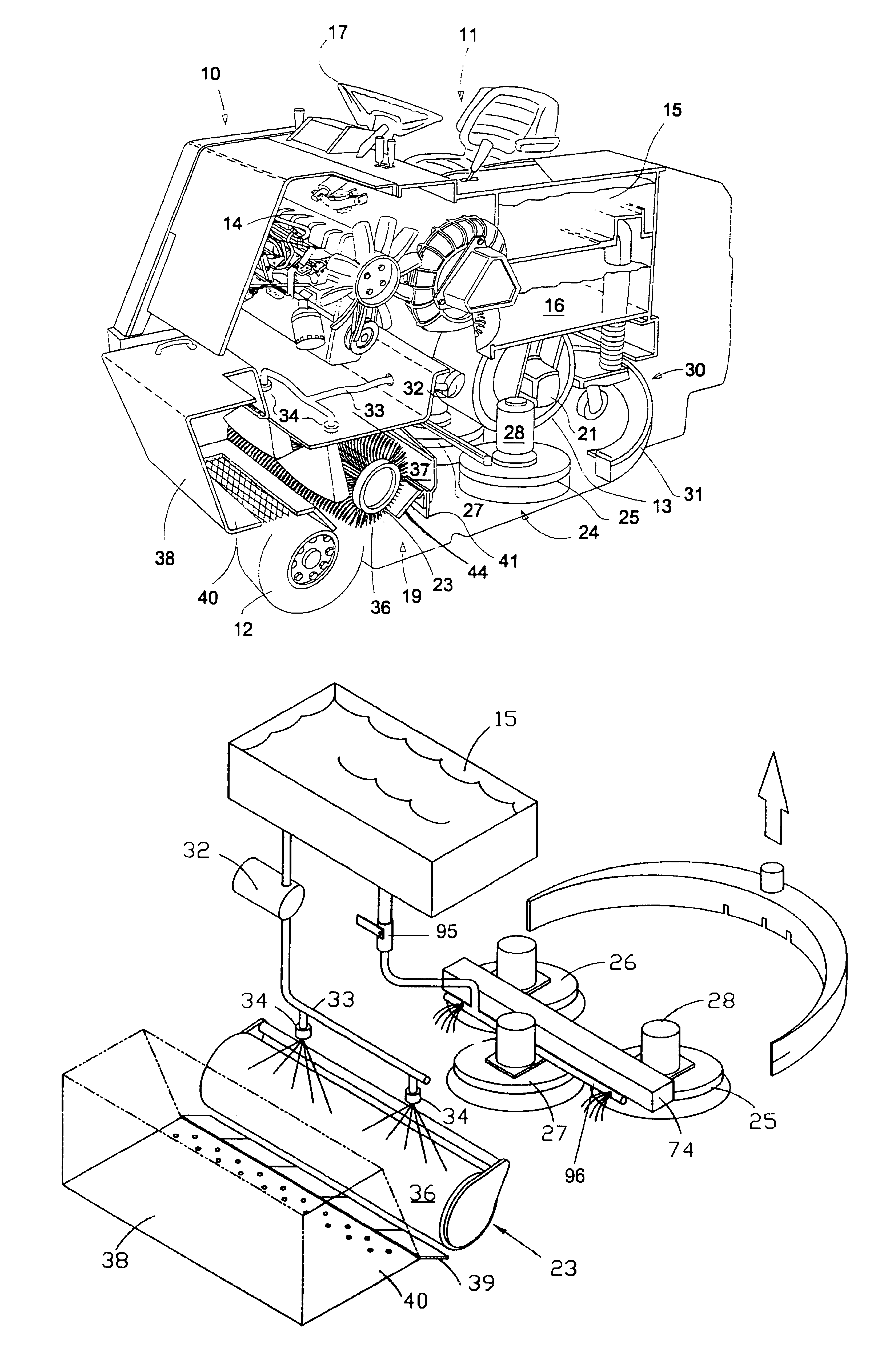
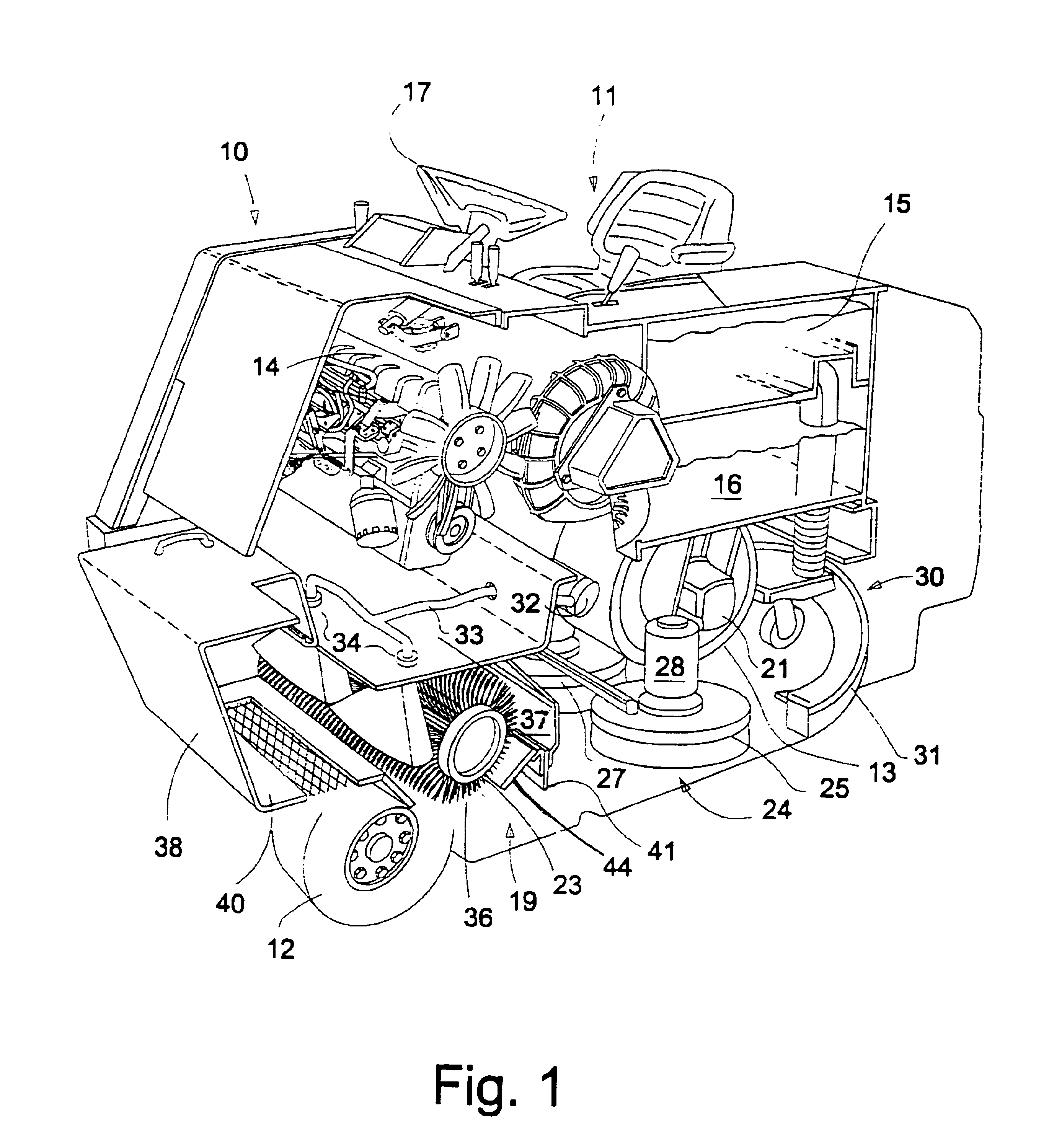
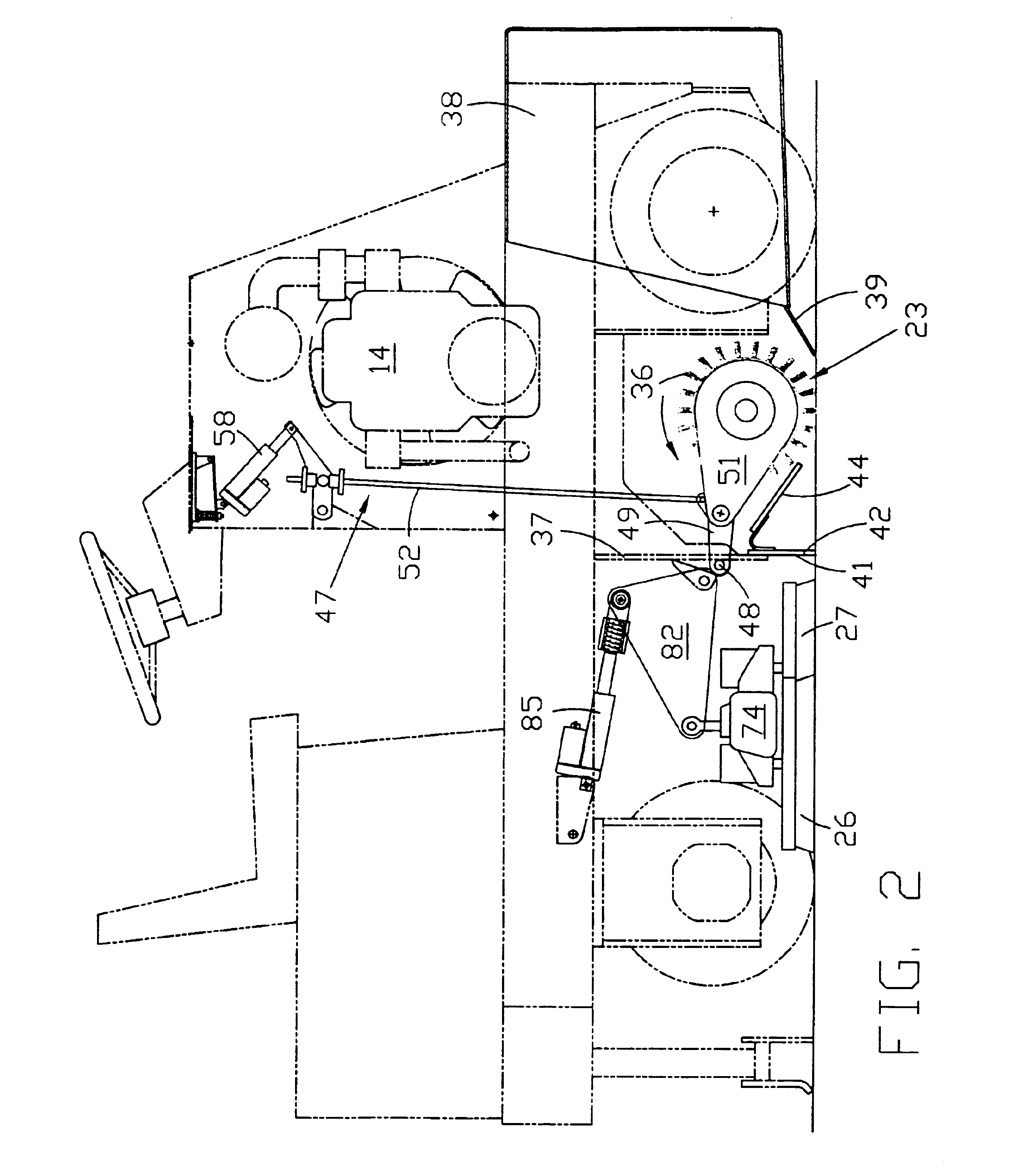
Referring first to FIG. 1, there is shown a floor scrubbing machine generally designated 10 in the form of a rider scrubber including an operator station generally designated 11, a pair of forward support wheels, one of which is seen at 12, a single rear steering wheel 13, an engine 14, a clean water or solution tank 15, and a recovery tank generally designated 16. The steerable wheel 13 is controlled by an operator seated at the operator station 11 by means of a steering wheel 17 and conventional steering mechanism. As is also known, the rear steerable wheel 13 is driven by a hydraulic motor 21 which is powered by the engine 14. The machine of FIG. 1 is covered by suitable paneling, and it is a self-contained vehicle. All of the components identified above are conventional, and need not be described further to persons skilled in the art.

The machine includes a forward scrubbing element 19 in the form of a conventional cylindrical brush 23 which will be described further below. Behin...


PUM


Abstract

A floor scrubber includes a forward cylindrical brush with adjustable down pressure. The cylindrical brush is sprayed uniformly with a controlled amount of water or solution and moves debris forward with a direct propelling action into a collection hopper. A set of three disc brushes is located behind the cylindrical brush, followed by a suction liquid recovery device for suctioning spent solution. A control system allows independent use of the forward cylindrical brush, or the rear disc brush set, or all brushes. A floor-engaging flap having a central opening extends transverse of the machine behind the cylindrical brush to channel water from the cylindrical brush to the disc brush set and then to the suction recovery device.

Description

FIELD OF THE INVENTIONThe present invention relates to floor scrubbing machines; and more particularly, it relates to a rider scrubber using driven scrub brushes and a cleaning solution to loosen and remove debris, followed by a vacuum recovery system for suctioning up the spent solution.SUMMARY OF THE INVENTIONRider scrubbers have been known in the industry for some time. One of the problems with a rider scrubber is that the suction recovery system can become plugged with loose or wet debris removed from the floor. It is important, therefore, to remove as much of the debris as possible ahead of the suction recovery system which is normally in the form of a curved squeegee coupled to a source of suction created by a powered fan, which generates a pressure reduced below atmosphere in a sealed tank. The suction pressure is communicated to the squeegee for recovering the spent solution from the floor.Attempts have been made to increase the scrubbing effectiveness of a rider scrubber by...

Claims


Application Information

Patent Timeline
Owner MINUTEMAN INT
Why Eureka
Try Eureka