
Full-automatic pipe bending structure capable of reducing connecting pipe opening deformation quantity during pipe bending

A deformation variable, fully automatic technology, applied in metal processing equipment, feeding devices, positioning devices, etc., can solve the problems of high labor intensity of employees, slow production rhythm, difficult insertion, etc., to reduce labor intensity and improve pipe bending efficiency. , the effect of ingenious design

Pending Publication Date: 2018-02-16
WUHU SANHUA AUTOMATION COMPONENTS
View PDF0 Cites 0 Cited by
  • Summary
  • Abstract
  • Description
  • Claims
  • Application Information

AI Technical Summary

Problems solved by technology

The straight line section of some pipes is relatively short, and the nozzle deformation is easy to occur when the pipe is bent. The old method uses a movable bush to support the flared end of the nozzle. Only manual pipe bending cannot realize automatic pipe bending.
When performing pipe bending operations, the bushing is placed on the mandrel of the bending pipe, and the bushing supports the flaring end of the pipe mouth. When the pipe is bent, the movable bushing moves with the pipe to prevent the deformation of the flaring end: the movable bushing is on the mandrel of the bending pipe Sliding cannot realize automatic pipe bending; due to manual operation, the movable bushing on the nozzle is difficult to insert, and the labor intensity of the staff is high, and they are prone to fatigue; the production cycle is slow

Method used


Image

  • Full-automatic pipe bending structure capable of reducing connecting pipe opening deformation quantity during pipe bending
  • Full-automatic pipe bending structure capable of reducing connecting pipe opening deformation quantity during pipe bending
  • Full-automatic pipe bending structure capable of reducing connecting pipe opening deformation quantity during pipe bending

Examples


Embodiment Construction

[0022] The present invention will be further described below in conjunction with accompanying drawing:

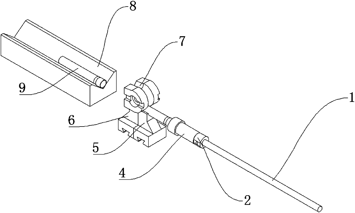
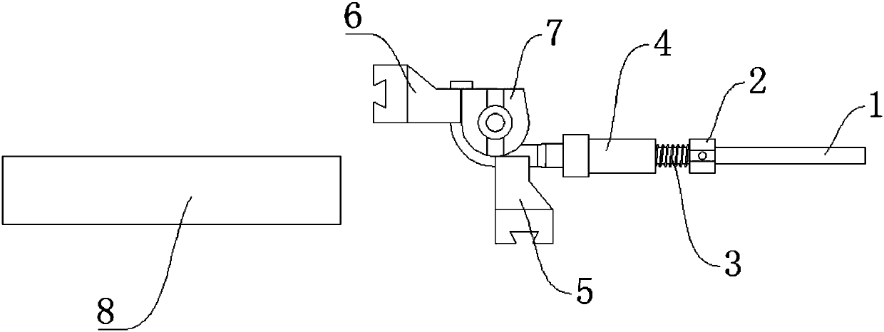
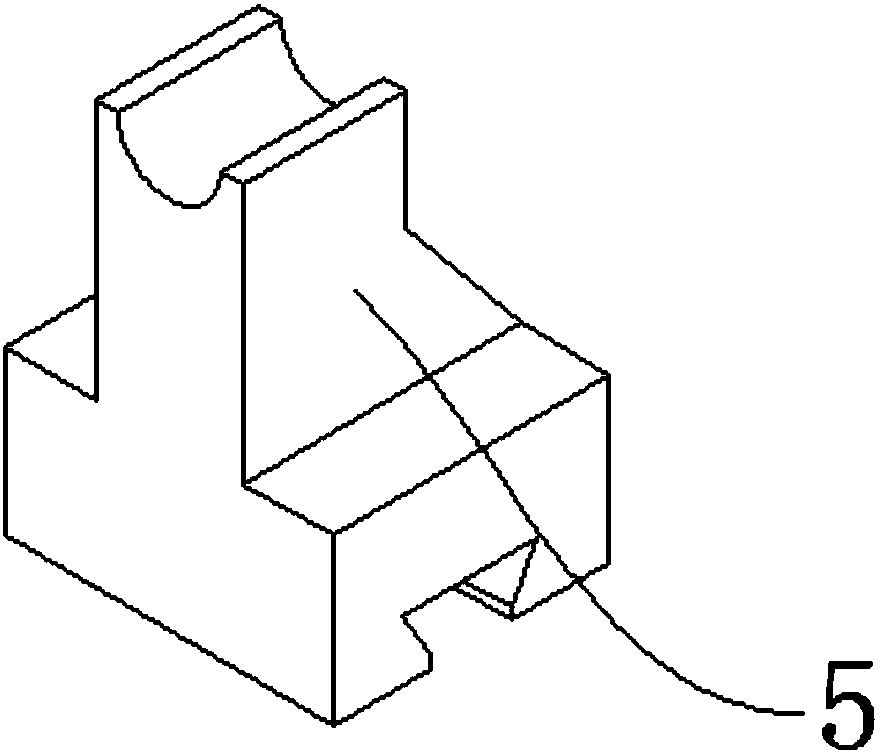
[0023] Such as Figure 1-Figure 6 As shown, a fully automatic pipe bending structure that reduces the deformation of the nozzle when bending the pipe, includes a feeding mechanism 8, a pipe bending round die 7, a connecting pipe 9 is placed on the feeding mechanism 8, and a pipe bending clamp is arranged next to the feeding mechanism 8 Die 6, pipe bend clamping die 6 is provided with bend pipe former 5, the top of pipe bend former 5 is provided with bend pipe round die 7, bend pipe mandrel 1 is arranged beside bend pipe master form 5, bend pipe mandrel 1 A movable bush 4 is arranged on the top, and an elbow positioning block 2 is arranged on the outside of the movable bush 4 , and a compression spring 3 is arranged between the elbow positioning block 2 and the movable bush 4 .

[0024] The upper surface of the feeding mechanism 8 is a V-shaped structure, the connecting pip...


PUM


Abstract

The invention discloses a full-automatic pipe bending structure capable of reducing the connecting pipe opening deformation quantity during pipe bending. The full-automatic pipe bending structure comprises a feeding mechanism and a pipe bending round mold, a connecting pipe is placed on the feeding mechanism, a pipe bending clamping mold is arranged beside the feeding mechanism, a pipe bending leaning mold is arranged beside the pipe bending clamping mold, the pipe bending round mold is arranged above the pipe bending leaning mold, a pipe bending mandril is arranged beside the pipe bending leaning mold and is provided with a movable bush, a pipe bending positioning block is arranged on the outer side of the movable bush, and a compression spring is arranged between the pipe bending positioning block and the movable bush. The full-automatic pipe bending structure is ingenious in design and conception, simple and easy to operate, full-automatic pipe bending of the special connecting pipeis achieved, the labor intensity of workers is greatly reduced, and the pipe bending efficiency is improved.

Description

technical field [0001] The invention relates to a pipe bending machine, in particular to a fully automatic pipe bending structure which reduces the deformation of the nozzle opening during pipe bending. Background technique [0002] The stop valve is an important part of the air conditioning system, which plays the role of opening and closing the refrigerant circulation channel. Piping elbow is an important link in the production process of globe valve. The straight line section of some pipes is short, and the nozzle deformation is easy to occur when the pipe is bent. The old method uses a movable bush to support the flared end of the nozzle. Only manual pipe bending cannot realize automatic pipe bending. When performing pipe bending operations, the bushing is placed on the mandrel of the bending pipe, and the bushing supports the flaring end of the pipe mouth. When the pipe is bent, the movable bushing moves with the pipe to prevent the deformation of the flaring end: the ...

Claims


Application Information

Patent Timeline
Patent Type & Authority Applications(China)
IPC IPC(8): B21D9/04B21D9/05B21D9/16B21D43/00
CPCB21D9/04B21D9/05B21D9/16B21D43/006
Inventor 郭辉丁永均陈玉富
Owner WUHU SANHUA AUTOMATION COMPONENTS
Learn More