
A rotatable oil injection mechanism

An oil injection mechanism and rotary technology, which is used in metal processing machinery parts, metal processing equipment, maintenance and safety accessories, etc., can solve problems such as affecting oil injection work, difficulty, and inconvenient operation, preventing oil leakage and ensuring sealing. , The effect of convenient oil filling operation

Active Publication Date: 2019-04-12
ANHUI RONGDA VALVE
View PDF7 Cites 0 Cited by
  • Summary
  • Abstract
  • Description
  • Claims
  • Application Information

AI Technical Summary

Problems solved by technology

[0005] The purpose of the present invention is to solve the uncertain orientation of the oil port of the elbow oil cup in the prior art, which leads to difficulties in filling butter through the elbow oil cup, inconvenient operation, and inconvenient communication of the oil injection channel of the oil injection mechanism control, thus affecting the smooth progress of the oil injection work, and a rotatable oil injection mechanism is proposed

Method used

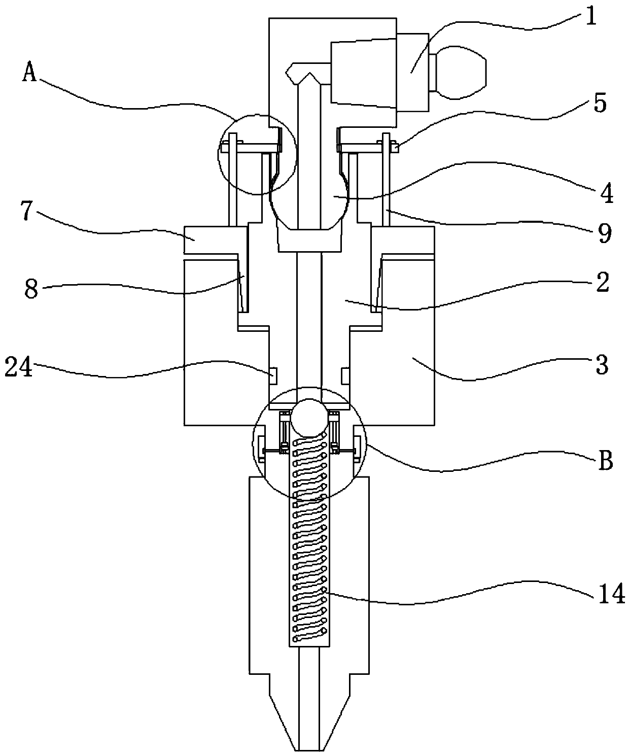

Image

  • A rotatable oil injection mechanism
  • A rotatable oil injection mechanism
  • A rotatable oil injection mechanism

Examples


Embodiment Construction

[0020] The following will clearly and completely describe the technical solutions in the embodiments of the present invention with reference to the accompanying drawings in the embodiments of the present invention. Obviously, the described embodiments are only some, not all, embodiments of the present invention.

[0021] In describing the present invention, it should be understood that the terms "upper", "lower", "front", "rear", "left", "right", "top", "bottom", "inner", " The orientation or positional relationship indicated by "outside", etc. is based on the orientation or positional relationship shown in the drawings, and is only for the convenience of describing the present invention and simplifying the description, rather than indicating or implying that the referred device or element must have a specific orientation, so as to Specific orientation configurations and operations, therefore, are not to be construed as limitations on the invention.

[0022] refer to Figure ...


PUM


Abstract

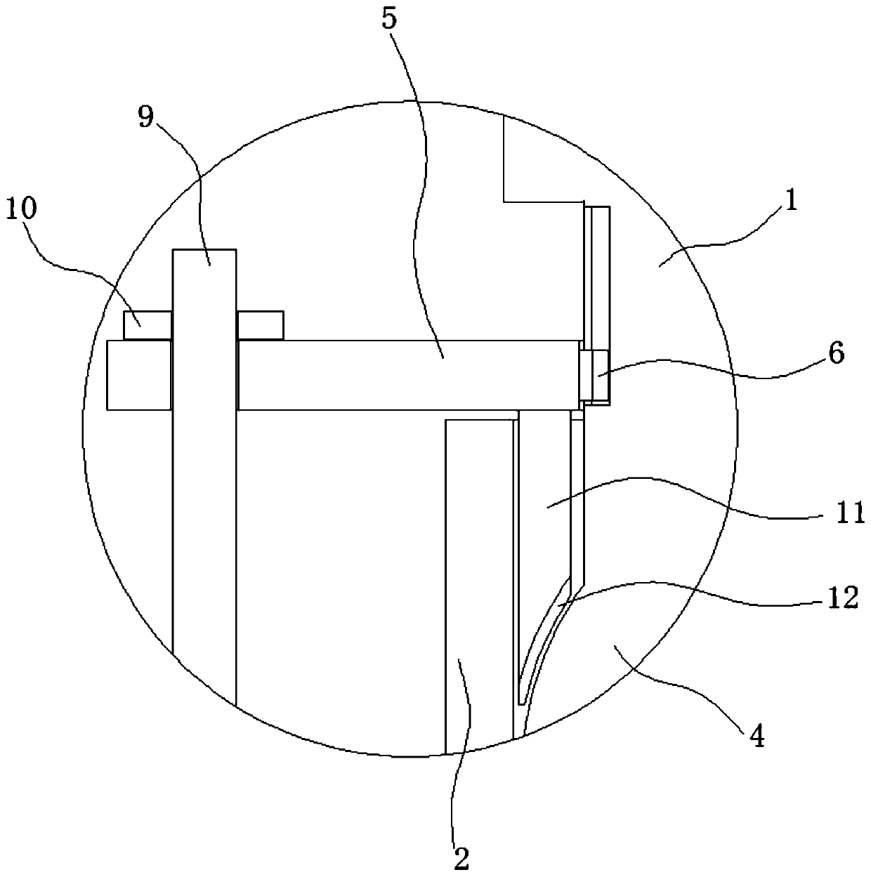
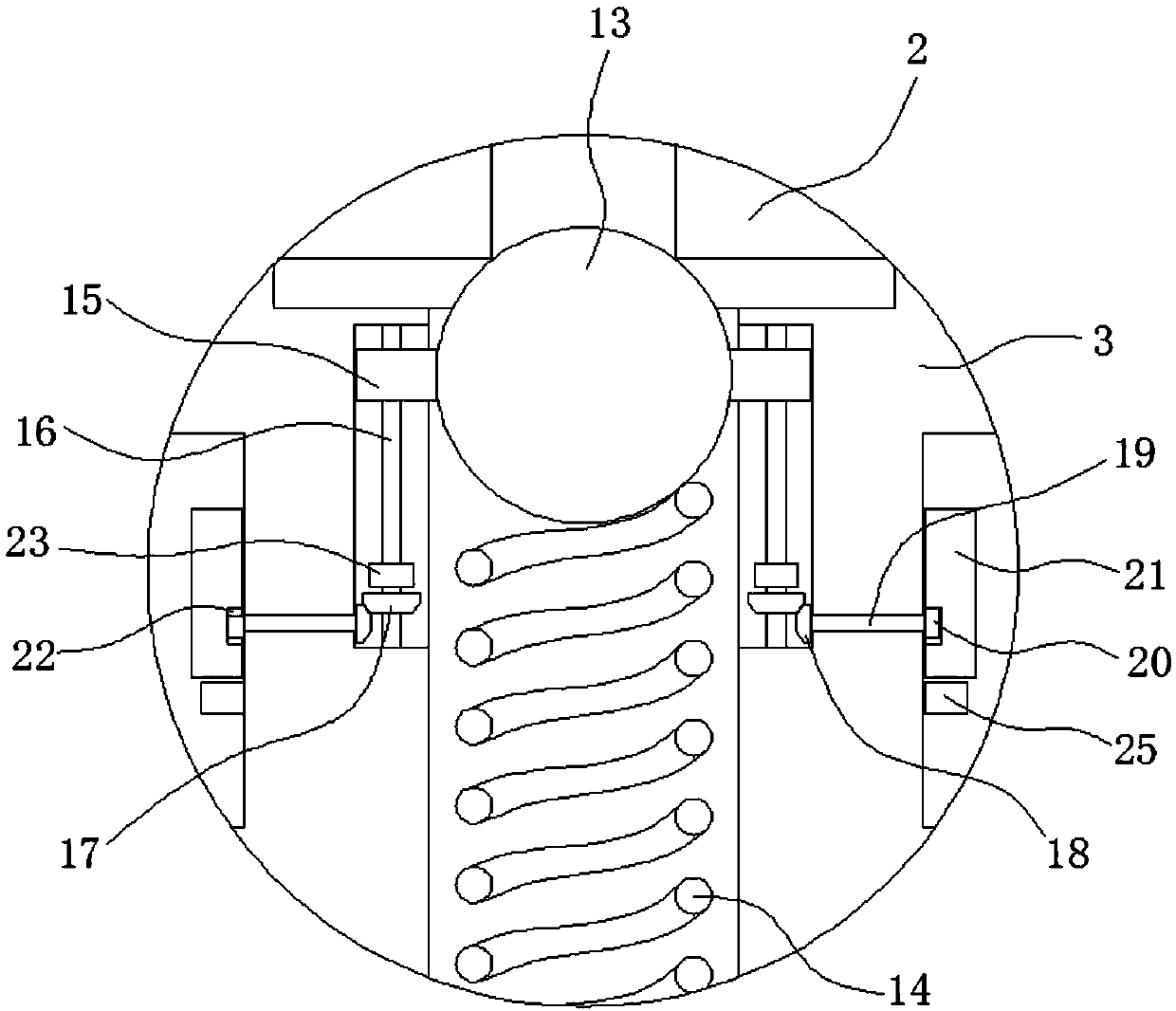
The invention discloses a rotatable oil injection mechanism. The rotatable oil injection mechanism comprises an elbow oil cup, a rotary body and a one-way valve which are arranged from top to bottom in sequence. The lower end of the elbow oil cup is provided with a spherical connecting part. The spherical connecting part is provided with an oil injection port communicating with the interior of theelbow oil cup. The upper side of the rotary body is provided with a first insertion groove corresponding to the elbow oil cup. The inner sidewall of the first insertion groove is provided with a connecting groove corresponding to the spherical connecting part. The end, close to the spherical connecting part, of the elbow oil cup is sleeved with a connecting ring. The inner sidewall of the connecting ring is annularly provided with a plurality of sliding blocks. The outer sidewall of the elbow oil cup is provided with first sliding grooves corresponding to the sliding blocks. The lower side ofthe connecting ring is provided with a mounting ring. The rotatable oil injection mechanism is simple in structure and convenient to use and facilitates injection of grease by rotating the elbow oilcup. Meanwhile, communication of an oil injection channel of the oil injection mechanism can be controlled conveniently. Accordingly, oil injection operation can be carried out conveniently and smoothly.

Description

technical field [0001] The invention relates to the technical field of oil injection mechanisms, in particular to a rotatable oil injection mechanism. Background technique [0002] During the working process of the machine tool, the main shaft will rotate continuously to facilitate the turning, milling, cutting, cutting and other work on the workpiece. It requires high-speed rotation of the main shaft, which requires the lubrication of the main shaft to reduce the friction during the main shaft rotation. Therefore, it is necessary to use an oil injection mechanism to fill the main shaft with oil, so as to facilitate the realization of the above lubrication effect. [0003] During use, the oil injection mechanism often rotates with the rotation of the machine. When the machine stops, the oil port of the elbow oil cup may face any direction, that is, the direction of the oil port of the elbow oil cup is uncertain, so Difficulty occurs when filling butter through the elbow oil...

Claims


Application Information

Patent Timeline
Patent Type & Authority Patents(China)
IPC IPC(8): B23Q11/12
CPCB23Q11/122
Inventor 吴成祝
Owner ANHUI RONGDA VALVE
Learn More