Baguette cutting machine
A cutting machine, bread technology, applied in the direction of metal processing, etc., can solve problems such as processing that cannot be automated, and achieve the effect of both efficiency
- Summary
- Abstract
- Description
- Claims
- Application Information
AI Technical Summary
Problems solved by technology
Method used
Image

Examples
Embodiment Construction
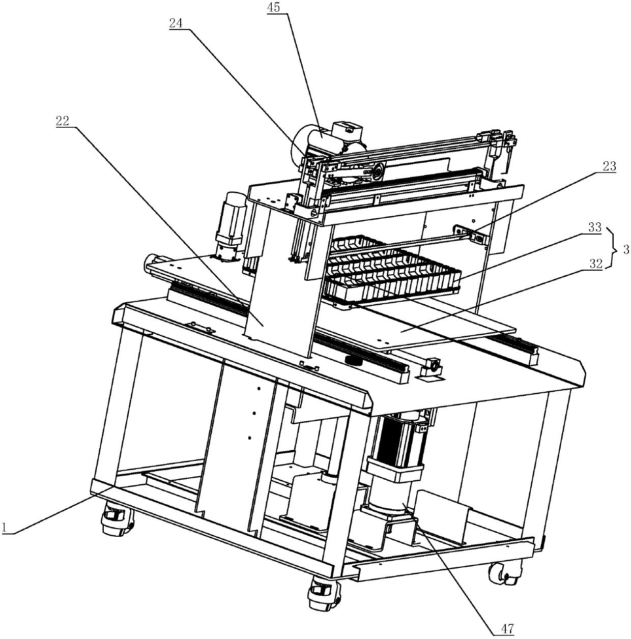
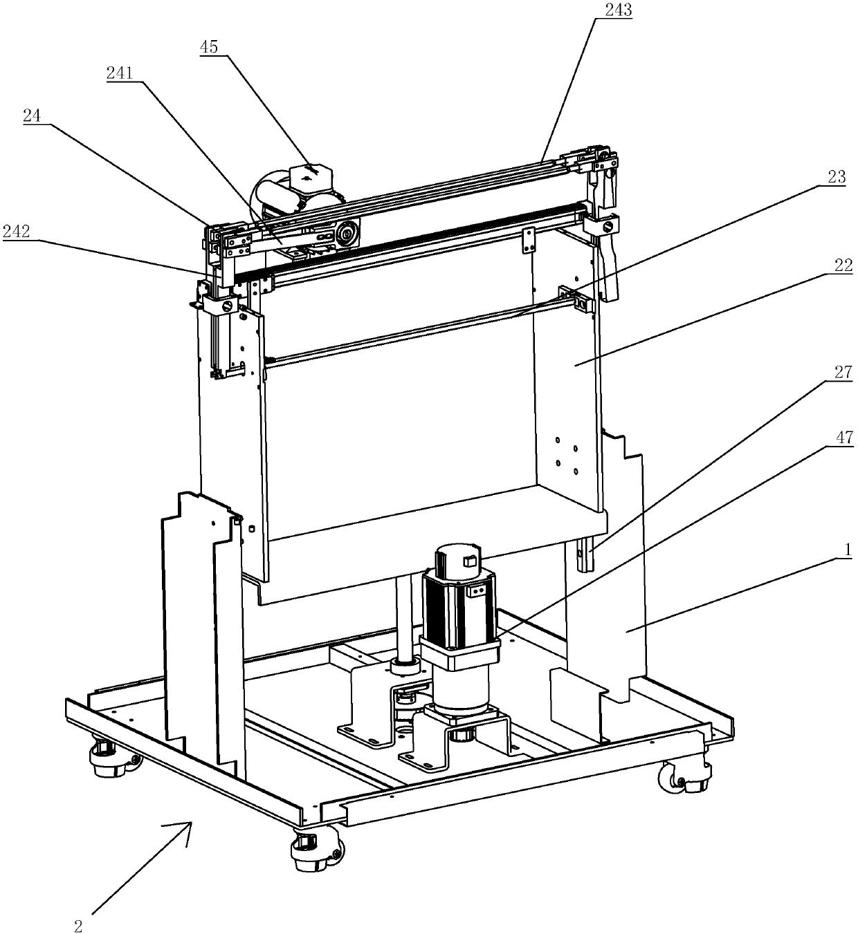
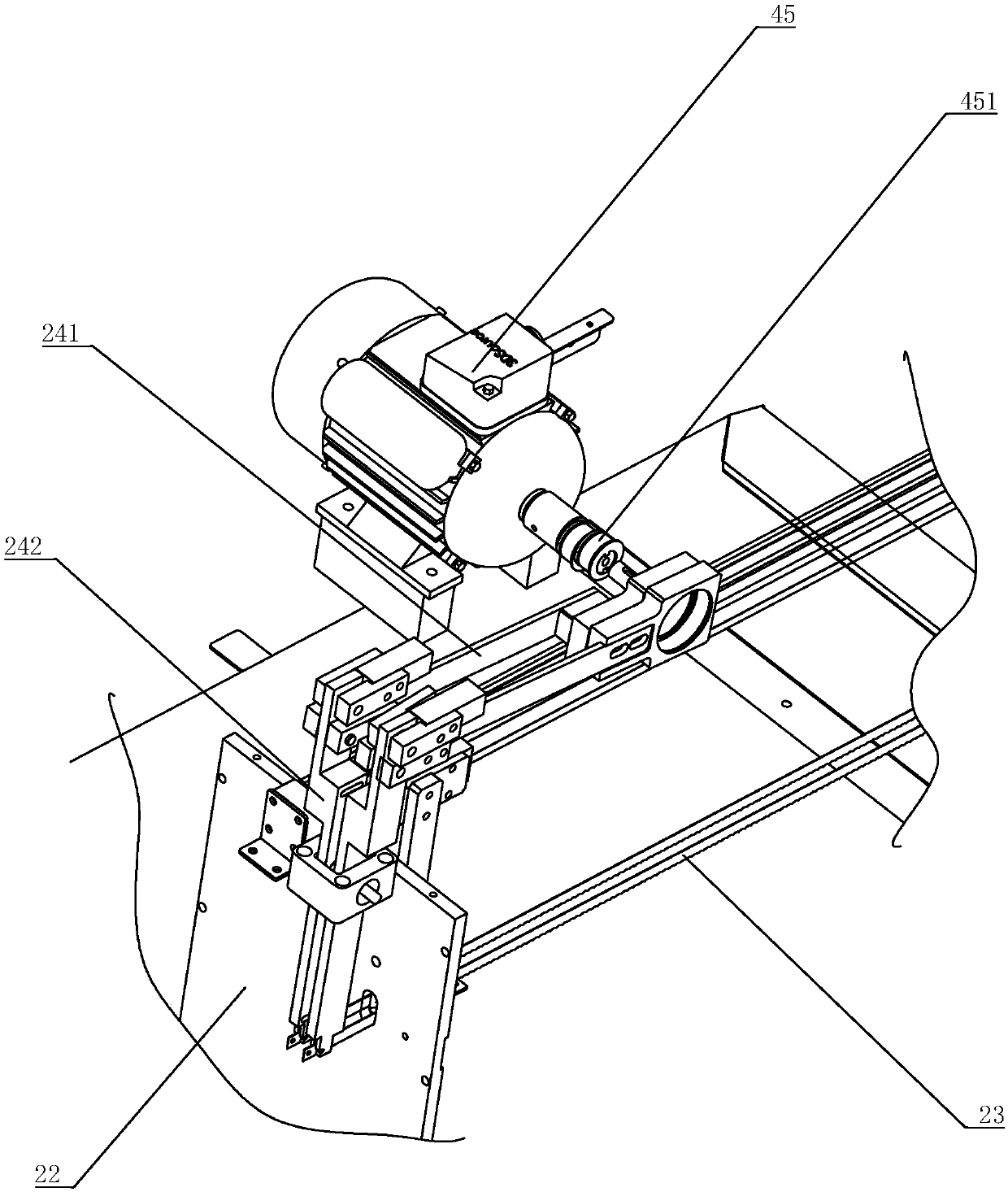
[0023] refer to Figure 1 to Figure 4 , a baguette cutting machine of the present invention, comprising a frame 1, a cutting device 2, a positioning device 3, and a first motor 45 and a third motor 47, the positioning device 3 is slidingly connected with the frame 1, the The cutting device 2 is installed above the positioning device 3 and is connected with the third motor 47, and is driven by the third motor 47 to move up and down to cut the bread, while the positioning device 3 moves horizontally and cooperates with the cutting device 2 to cut the whole baguette; The cutting device 2 includes a knife rest 22, a cutting knife 23 mounted on the knife rest 22, and a link mechanism 24. The link mechanism 24 is connected to and driven by the first motor 45. The cutting knife 23 blade is Zigzag and horizontal reciprocating movement under the drive of connecting rod mechanism 24 so as to cut bread; The positioning device 3 includes a positioning seat 32 and a positioning mold 33 ins...
PUM
 Abstract
Description
Claims
Application Information
 - R&D
- Intellectual Property
- Life Sciences
- Materials
- Tech Scout
- Unparalleled Data Quality
- Higher Quality Content
- 60% Fewer Hallucinations
Browse by: Latest US Patents, China's latest patents, Technical Efficacy Thesaurus, Application Domain, Technology Topic, Popular Technical Reports.
© 2025 PatSnap. All rights reserved.Legal|Privacy policy|Modern Slavery Act Transparency Statement|Sitemap|About US| Contact US: help@patsnap.com