Movable water stop system of final connector and application method

A water stop and water stop technology, applied in water conservancy projects, underwater structures, artificial islands, etc., can solve problems such as difficult water stop, poor water stop effect, short service life, etc., to ensure water stop, strengthen water stop Water effect, the effect of prolonging the water stop time

Active Publication Date: 2018-02-16
CCCC HIGHWAY CONSULTANTS
View PDF3 Cites 5 Cited by
  • Summary
  • Abstract
  • Description
  • Claims
  • Application Information

AI Technical Summary

Problems solved by technology

[0006] The purpose of the present invention is to provide a movement of the final joint to solve the problems that it is difficult to stop the water when the final joint and the pushing trabecular are relatively moved, and that the single water-stop device has poor water-stop effect and short service life. The water stop system and its use method, the water stop system includes an external water stop device and an internal water stop device arranged between the final joint and the push beam, the external water stop device plays the main role of water stop, and the internal water stop device serves as a backup , Composite water-stop function, when the external water-stop device leaks or is damaged, the internal water-stop device plays a water-stop function at the same time, further realizing the water-stop function, effectively preventing the external water flow from entering between the final joint and the adjacent pipe joint In the joint cavity, achieve the effect of composite water stop, and ensure the smooth installation of the final joint

Method used


Image

  • Movable water stop system of final connector and application method
  • Movable water stop system of final connector and application method
  • Movable water stop system of final connector and application method

Examples


Embodiment 1

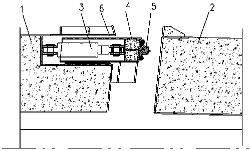
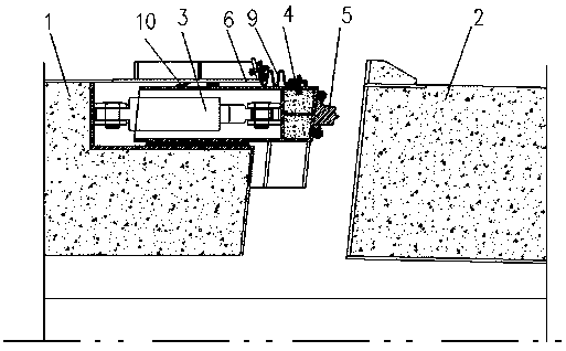
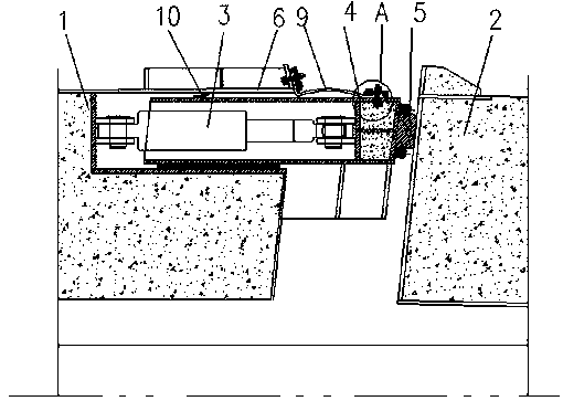
[0050] Such as figure 2 and image 3 As shown in the mobile water stop system of the final joint, the final joint 1 and the push beam 4 are equipped with an external water stop device 9 that makes the annular cavity relatively sealed from the outside water flow, and the external water stop device 9 includes a flexible Waterstop, one end of the flexible waterstop is connected to the final joint 1, and the other end is connected to the push beam 4, the extension length of the flexible waterstop corresponds to the length of the outward movement of the push beam 4, and the ring An internal water stop device 10 is also installed in the cavity of the cavity.

[0051] The external water stop device uses a flexible water stop, and the two ends of the flexible water stop are respectively connected with the final joint 1 and the push beam 4 to complete the sealing. When the push beam 4 moves relatively, the flexible water stop follows the The push beam 4 moves to the adjacent pipe jo...

Embodiment 2

[0071] Such as figure 2 and image 3 As shown, the method of using the mobile water stop system for the final joint includes the following steps:

[0072] a. Install the internal water stop device 10, and install the internal water stop device 10 at the design position of the push beam 4;

[0073] b. Push the pushing beam 4 into the inner cavity of the final joint 1, so that the pushing beam 4 is at the initial position before pushing;

[0074] c. Install the jack 3, and use the jack 3 to connect the pushing girder 4 and the final joint 1;

[0075] d. Install the external water stop device 9, and connect the two ends of the flexible water stop belt to the pushing girder 4 and the final joint 1, so that an independent closed space is formed between the external water stop device 9 and the internal water stop device 10.

[0076] Through the above method, a mobile water-stop structure is formed between the pushing girder and the final joint to achieve the effect of sealing wa...


PUM


Abstract

The invention relates to the technical field of immersed tunnels, in particular to a movable water stop system of a final connector and an application method. The final connector and a pushing small beam are provided with an outer water stop device making an annular cavity and outer water flow relatively sealed. The outer water stop device comprises a flexible water stop belt, one end of the flexible water stop belt is connected with the final connector, the other end of the flexible water stop belt is connected with the pushing small beam, and the stretching length of the flexible water stopbelt corresponds to the outward movement length of the pushing small beam. An inner water stop device is further arranged in a cavity body of the annular cavity. The movable water stop system is formed by the outer water stop device and the inner water stop device of the water stop system at the same time. The dual water stop devices are adopted, the function of composite water stop is achieved, and when the outer water stop device leaks or is damaged, the inner water stop device plays a role, the purpose of water stop is further achieved, and smooth installation of the final connector is guaranteed.

Description

technical field [0001] The invention relates to the technical field of immersed tube tunnels, in particular to a mobile water-stop system for a final joint and a method for using it. Background technique [0002] Immersed tube tunnel construction is to float and transport the prefabricated tunnel caissons in semi-submerged barge or dry dock to the predetermined position for sinking and docking. In order to make the last pipe section sink smoothly, a distance longer than this pipe section must be left Space, the pipe section placed butted in the remaining distance space is regarded as the final joint. The final joint of the immersed tube tunnel is the key to the construction of the immersed tube tunnel. Because the final joint itself has the characteristics of large volume and complex structure, especially in the construction of the ultra-long immersed tube tunnel in the open sea, the construction of the final joint is very difficult. The fine design of the final joint's own...

Claims


Application Information

Patent Timeline
Patent Type & Authority Applications(China)
IPC IPC(8): E02D29/073E02D31/06E02D29/16
CPCE02D29/073E02D29/16E02D31/06
Inventor 林鸣刘晓东林巍李毅尹海卿张志刚程潜姬海
Owner CCCC HIGHWAY CONSULTANTS
Why Eureka
Try Eureka