Pump shaft sleeve for double suction pump

A technology of double-suction pumps and shaft sleeves, which is applied to components, pumps, and pump components of pumping devices for elastic fluids, and can solve problems such as increased water flow resistance, difficulty in dismantling and repairing the pump body, and seal failure. The effect of increasing the lubrication time, avoiding adverse effects, and prolonging the service life

Inactive Publication Date: 2018-02-16
ANHUI TENGLONG PUMP VALVE MFG CO LTD
View PDF5 Cites 0 Cited by
  • Summary
  • Abstract
  • Description
  • Claims
  • Application Information

AI Technical Summary

Problems solved by technology

[0002] In the accessories of double-suction pumps, the shaft sleeve is set outside the pump shaft. The main function is to avoid the direct wear of the pump shaft at the seal. The shaft sleeve is used to directly rub against the packing, which can seal without wearing the pump shaft. At the same time, it can also play an axial positioning role for the impeller, but the existing shaft sleeve is usually a hollow cylindrical structure, which is directly sleeved outside the pump shaft, forming a certain step at the impeller, thereby increasing the resistance to the water flow there, and At the corresponding position of the seal, due to premature wear, it often leads to seal failure. During the working process of the centrifugal pump, cavitation will affect the erosion of the inner and outer surfaces of the shaft sleeve, which will bring difficulties to the dismantling and repair of the pump body, and even make the pump shaft scrapped

Method used


Image

  • Pump shaft sleeve for double suction pump

Examples


Embodiment Construction

[0010] The present invention will be further described below in conjunction with the accompanying drawings.

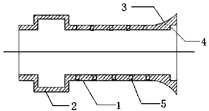
[0011] like figure 1 As shown in , a pump shaft bushing for a double suction pump includes a bushing body 1, the interior of the bushing body 1 is a cylindrical cavity structure, and an annular groove 2 is provided on the inner wall on the left side of the bushing body 1, On the outer side of the right end of the sleeve main body 1 is an arc-shaped structure 3 smoothly connected with the sleeve main body 1. The inner wall of the sleeve main body 1 corresponding to the arc-shaped structure 3 is provided with an annular step 4, and the annular step 4 and the impeller are arranged on the pump. The steps formed when the shaft is on the shaft match, and several through holes 5 are evenly arranged around the main body 1 of the sleeve.

[0012] Preferably, the through holes 5 are distributed in an array on the sleeve body 1 .

[0013] In practice, the annular groove 2 of th...


PUM


Abstract

The invention discloses a pump shaft sleeve for a double suction pump. The pump shaft sleeve comprises a shaft sleeve body. A cylindrical cavity structure is arranged in the shaft sleeve body. An annular groove is formed in the inner wall of the left side of the shaft sleeve body. An arc structure smoothly connected with the shaft sleeve body is arranged on the outer side of the right end of the shaft sleeve body. An annular step is arranged at the position, corresponding to the arc structure, of the inner wall of the shaft sleeve body. Multiple through holes are evenly formed in the peripheryof the shaft sleeve body. Compared with the prior art, the pump shaft sleeve has the following beneficial effects that the annular groove of the shaft sleeve cooperates with a pump shaft to form a closed oil cavity, the lubricating time of the shaft and a bearing can be effectively increased, and the service life of the shaft can be prolonged; the through holes are formed in the shaft sleeve body, and therefore concentration of bubbles on the surface of the shaft sleeve can be reduced, and the bad influence generated by cavitation on the shaft sleeve is avoided; and a part matched with the step formed by an impeller and the pump shaft is arranged at the right end of the shaft sleeve, the axial locating function can be achieved on the impeller, the outer side of the shaft sleeve and the impeller are in smooth transition, resistance to water flow is reduced, and the work efficiency of the double suction pump is improved.

Description

technical field [0001] The invention belongs to the technical field of double-suction pump accessories, and in particular relates to a pump shaft sleeve for a double-suction pump. Background technique [0002] In the accessories of double-suction pumps, the shaft sleeve is set outside the pump shaft. The main function is to avoid the direct wear of the pump shaft at the seal. The shaft sleeve is used to directly rub against the packing, which can seal without wearing the pump shaft. At the same time, it can also play an axial positioning role for the impeller, but the existing shaft sleeve is usually a hollow cylindrical structure, which is directly sleeved outside the pump shaft, forming a certain step at the impeller, thereby increasing the resistance to the water flow there, and In the corresponding position of the seal, due to premature wear, it often leads to seal failure. During the working process of the centrifugal pump, cavitation will affect the erosion of the inne...

Claims


Application Information

Patent Timeline
Patent Type & Authority Applications(China)
IPC IPC(8): F04D29/04F04D29/06F04D29/66F04D1/00
CPCF04D29/04F04D1/006F04D29/061F04D29/669
Inventor 徐向远
Owner ANHUI TENGLONG PUMP VALVE MFG CO LTD
Why Eureka
Try Eureka