Fan blade of industrial electric fan

A technology for industrial electricity and fans, which is applied to components of pumping devices for elastic fluids, non-variable pumps, pump components, etc. It can solve problems that affect performance, large air gaps, and increased frequencies. Achieve the effect of improving the wind blowing effect, large air supply area, and increasing the wind blowing volume

Pending Publication Date: 2018-02-16
广东飞鹿电器有限公司
View PDF4 Cites 2 Cited by
  • Summary
  • Abstract
  • Description
  • Claims
  • Application Information

AI Technical Summary

Problems solved by technology

[0002] In the existing industrial fan industry, the traditional fan blades generally adopt a two-leaf or three-blade structure, which have the following defects: the two-blade structure, the distribution angle between the blades is 180°, and the large distribution angle leads to high-speed operation of the fan blades When the airflow gap is too large, the frequency increases, resulting in greater low-frequency noise; the three-leaf structure, the wind generated is slowly scattered and not concentrated, and the tail end of the blade will generate a large vortex, resulting in greater noise
Because the inclination and twist of the blade body in this structure are not well coordinated, the working effect of the fan blade is not good. The specific performance is that the wind force is enhanced and the noise is louder, which affects the performance of use.

Method used


Image

  • Fan blade of industrial electric fan
  • Fan blade of industrial electric fan
  • Fan blade of industrial electric fan

Examples


no. 1 example

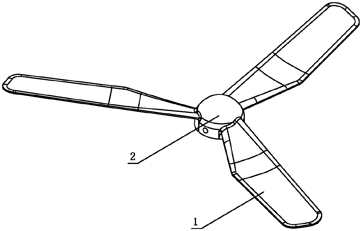
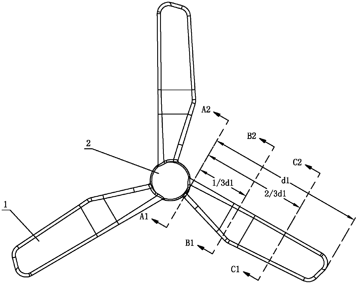
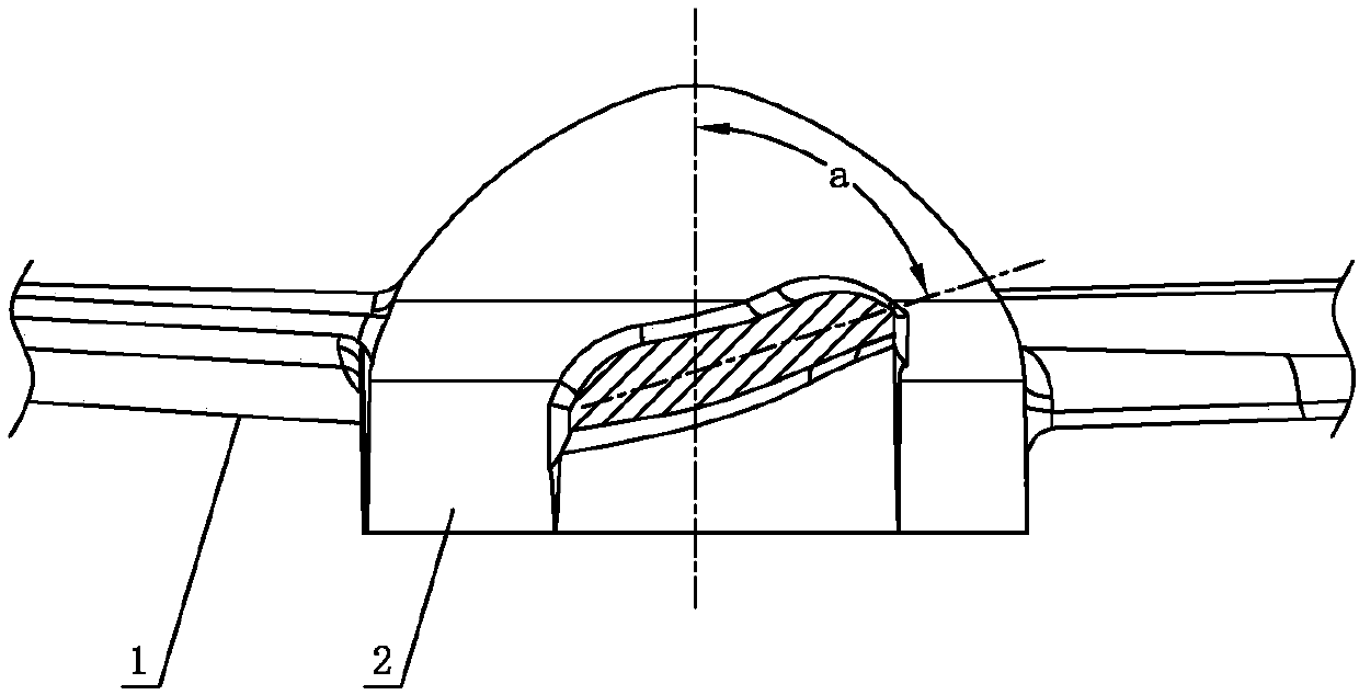
[0032] see Figure 1-Figure 8 , the blade diameter of the industrial electric fan involved in this embodiment is 750 ± 5% mm, the blade includes a blade 1 and a hub 2, the root of the blade 1 is connected to the hub 2, and the blade 1 extends radially from the root; the blade 1 is provided with three pieces, and each blade 1 is rotationally symmetrical and uniformly distributed in a ring; the root of the blade 1 is arranged obliquely relative to the rotation axis of the hub 2, and the angle a between each other is 72°; the blade 1 is twisted clockwise while extending radially; the blade 1 has a length of d 1 is 338±5%mm, the blade 1 is twisted clockwise so that the included angles between different positions and the rotation axis of the hub 2 are different, wherein, in the blade 1 1 / 3d 1 The angle b between the section of the position and the axis of rotation of the hub 2 is 81°, at the blade 1 2 / 3d 1 The angle c between the section of the position and the rotation axis of t...

no. 2 example

[0041] see Figure 9-Figure 15The blade diameter of the industrial electric fan involved in this embodiment is 650±5% mm, which is different from the first embodiment in that: the root of the blade 1 is inclined relative to the rotation axis of the hub 2, and the angle a between them is is 71°; blade 1 twists clockwise while extending radially; the length of blade 1 is d 1 is 283±5%mm, blade 1 is twisted clockwise so that the included angles between different positions and the rotation axis of hub 2 are different, among which, blade 1 1 / 3 d 1 The angle b between the section of the position and the rotation axis of the hub 2 is 79°, at the blade 1 2 / 3 d 1 The angle c between the section of the position and the rotation axis of the hub 2 is 80°.

[0042] The length d of the windy area 1.1 3 with the length d of the transition zone 1.2 2 The ratio between them is: 17:10.

[0043] The ratio of the length d1 of the blade 1 to the maximum width d4 of the blade 1 is 4:1....


PUM


Abstract

The invention discloses a fan blade of an industrial electric fan. The fan blade comprises blade parts and a wheel hub; the root parts of the blade parts are connected with the wheel hub; the blade parts radially extend from the root parts; the number of the blade parts is three; the blade parts are rotationally symmetric and are annularly and uniformly arranged; the root parts of the blade partsare inclined relative to a rotating shaft of the wheel hub; an included angle a between each blade part and the rotating shaft of the wheel hub is 65-85 degrees; and the blade parts are twisted duringradial extension. The blade parts are subjected to reasonable inclination extension and clockwise twisting, and with the combination of the remiform fan blade parts, the push force of the fan blade is increased effectively; furthermore, the include angle between the blade parts is large (120 degrees), and an air flow forms good large liquidity, so that powerful wind power is generated, the air supply area is large, and wide-angle air supply is realized; particularly, the sections of the blade parts are arc-shaped, so that the wind blowing effect can be improved, guiding is carried out on theair flow, and the air flow is pushed forwards in a diffusion manner; and due to the twisted shapes of the blade parts, the air flow can be blown out entirely in a spiral manner, the blowing quantity is increased effectively, and noise caused by gas collision is avoided.

Description

technical field [0001] The invention relates to an electric fan, in particular to a fan blade of an industrial electric fan. Background technique [0002] In the existing industrial fan industry, the traditional fan blades generally adopt a two-leaf or three-blade structure, which have the following defects: the two-blade structure, the distribution angle between the blades is 180°, and the large distribution angle leads to high-speed operation of the fan blades When the airflow gap is too large, the frequency increases, resulting in greater low-frequency noise; the three-blade structure, the wind generated is slowly scattered and not concentrated, and the tail end of the blade will generate a large vortex, forming a large noise. For example, Chinese Patent Document No. CN204628075U disclosed a streamlined industrial fan blade on September 9, 2015, specifically disclosing: including the blade body and the blade root and blade tip arranged at both ends of the blade body, the ...

Claims


Application Information

Patent Timeline
Patent Type & Authority Applications(China)
IPC IPC(8): F04D29/26F04D29/66
CPCF04D29/26F04D29/663F04D29/667F05D2240/30F05D2240/301
Inventor 梁文广
Owner 广东飞鹿电器有限公司
Why Eureka
Try Eureka