Automatic bearing waste grease collecting system and automatic bearing grease changing system

A technology of automatic collection and waste grease, which is applied in the direction of bearing components, shafts and bearings, engine components, etc., can solve the problem of damage to the bearing structure, and achieve the effect of ensuring the amount of grease, ensuring the pressure, and the pressure state is reasonable

Pending Publication Date: 2018-02-16
AUTOL TECH
View PDF6 Cites 12 Cited by
  • Summary
  • Abstract
  • Description
  • Claims
  • Application Information

AI Technical Summary

Problems solved by technology

[0003] The purpose of the present invention is to provide a bearing structure to solve the interlocking of the injection device and the suction device in the prior art. The power of the injection device and the suction device is one, and they start and stop at the same time. In order to ensure that there is For a certain amount of lubricating grease, the suction volume of the suction device is slightly smaller, and the bearing structure will be damaged over time. At the same time, the purpose of the present invention is to provide an automatic bearing grease changing system for the bearing structure.

Method used


Image

  • Automatic bearing waste grease collecting system and automatic bearing grease changing system
  • Automatic bearing waste grease collecting system and automatic bearing grease changing system
  • Automatic bearing waste grease collecting system and automatic bearing grease changing system

Examples


Embodiment 3

[0048] Embodiment 3 of an automatic collection system for bearing waste grease. The difference between this embodiment and Embodiment 1 is that an oil pressure sensor is provided in the oil pressure system of the hydraulic cylinder.

Embodiment 4

[0049] Embodiment 4 of an automatic collection system for bearing waste grease. The difference between this embodiment and Embodiment 1 is that a position sensor is provided on the piston of the hydraulic cylinder.

[0050] The grease suction device of the bearing waste oil automatic collection system in the above embodiment can also be driven by a pneumatic cylinder, and the pneumatic cylinder and the hydraulic cylinder belong to the same technical features.

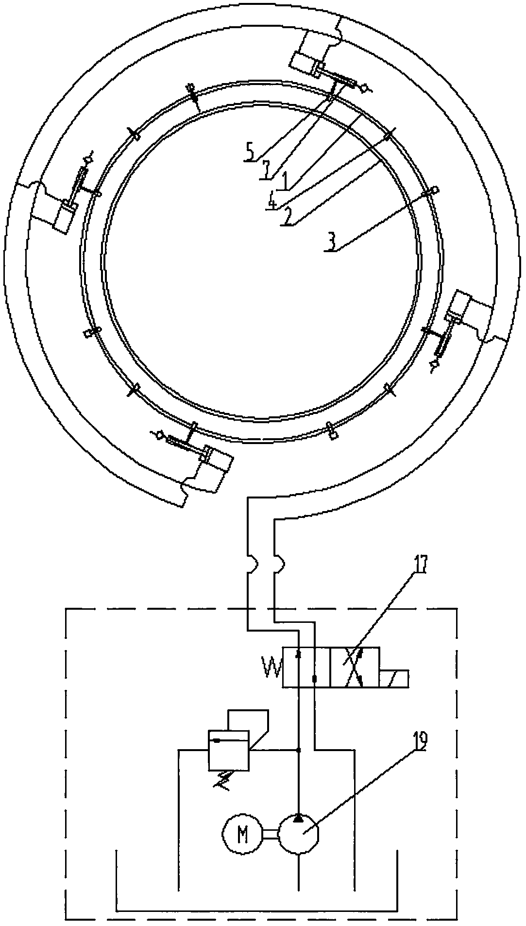
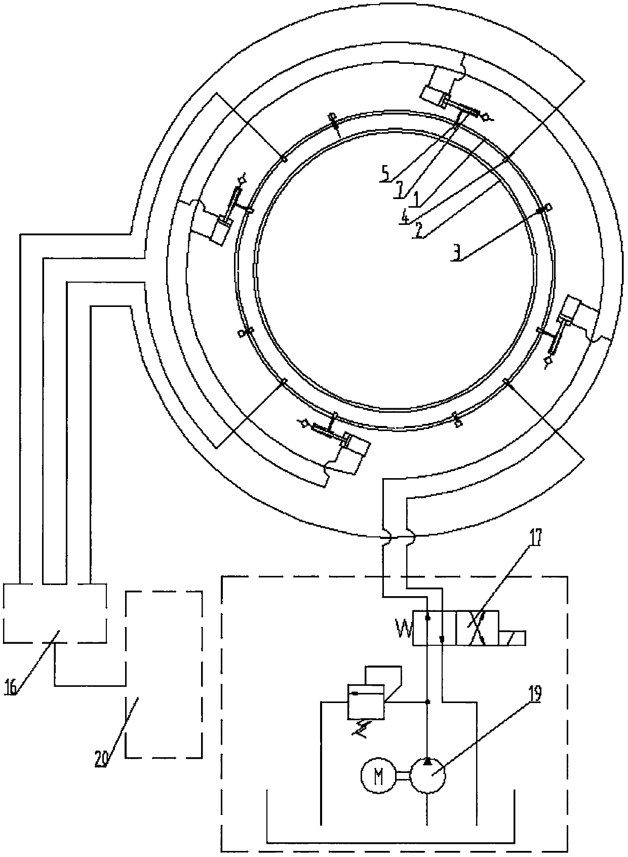
[0051] Embodiment 1 of a bearing automatic grease changing system, in figure 2 , Figure 5 as well as Figure 7 Among them, the bearings in the bearing structure of the bearing automatic grease changing system are sliding bearings without rolling elements. The outer ring 1, the inner ring 2 and the oil seals at both ends form a lubricating space, and the lubricating space is used to set grease. An oil inlet 4, an oil outlet 5 and a breathing port 3 are provided on the outer ring 1 of the bearing structure, and the oi...

Embodiment 5

[0058] Embodiment 5 of an automatic bearing grease changing system. The difference between this embodiment and Embodiment 1 of the bearing automatic grease changing system is that an oil pressure sensor is provided in the oil pressure system of the hydraulic cylinder.


PUM


Abstract

The invention discloses an automatic bearing waste grease collecting system and an automatic bearing grease changing system. The automatic bearing waste grease collecting system of the automatic bearing grease changing system comprises a bearing structure, a lubricating space used for containing lubricating grease is arranged between an outer ring and an inner ring of the bearing structure, the bearing structure is provided with grease outlets which communicate with the lubricating space, a suction and discharge device is arranged at each grease outlet in a communicating manner, and each suction and discharge device is provided with an independent power system. According to the automatic bearing waste grease collecting system and the automatic bearing grease changing system, each suction and discharge device is provided with one independent power system and has nothing to do with an injection device, so that the suction and discharge devices can be started conveniently, the starting frequency of each suction and discharge device is adjusted according to practical requirements, suction and discharge work is conducted according to practical requirements, and therefore it is guaranteed that the internal pressure state of the bearing structure is reasonable.

Description

technical field [0001] The invention relates to a bearing automatic grease changing system for injecting grease into the bearing and extracting the aging grease in the bearing, and also relates to an automatic collection system for bearing waste grease of the bearing automatic grease changing system. Background technique [0002] There are two main ways to lubricate bearings, one is liquid oil lubrication, this type of bearing must be installed in the box, and there is oil in the box, this type of lubrication has good effect and high cleanliness, but it is not suitable for All bearings, because some bearings cannot be installed inside the shell, the bearings used in wind power generation equipment, construction machinery, etc. belong to this type of bearings, this type of bearings need to be lubricated with grease, the viscosity of the grease is relatively high, It is not easy to flow out. When the lubrication space between the inner and outer rings of the bearing is complet...

Claims


Application Information

Patent Timeline
Patent Type & Authority Applications(China)
IPC IPC(8): F16N11/08F16N29/02F16N39/06F16N23/00F16C33/66F16C33/58
CPCF16C33/583F16C33/66F16N11/08F16N23/00F16N29/02F16N39/06F16N2210/14
Inventor 赵大平朱向华温志建
Owner AUTOL TECH
Why Eureka
Try Eureka