Assembly type mouth-shaped framework steel bridge abutment and construction method thereof

A mouth-shaped and assembled technology, applied in bridges, bridge parts, bridge materials, etc., can solve problems such as cracking of concrete main beams or bridge decks, reduce bridge head jumps, have strong fatigue resistance, and improve overall deformation. effect of ability

Pending Publication Date: 2020-12-22
FUZHOU UNIV
View PDF0 Cites 0 Cited by
  • Summary
  • Abstract
  • Description
  • Claims
  • Application Information

AI Technical Summary

Problems solved by technology

[0003] Although the integral bridge eliminates the expansion joints in structure, it has many advantages, but the horizontal reciprocating deformation of the main girder under the loads of different properties such as ambient temperature, concrete shrinkage deformation, automobile impact braking and earthquake will be transmitted To the substructure, causing the substructure, especially the abutment and the pile foundation at the bottom of the abutment, to reciprocate horizontally, and then cause complex abutment-backfill, pile foundation-soil, abutment-soil-pile foundation-soil and other structures -Soil interaction; therefore, for the overall bridge, special attention should be paid to the ability of the substructure abutment and pile foundation to adapt to the horizontal reciprocating deformation and to reduce or weaken the complex abutment-soil-pile foundation-soil interaction and other sciences Problem; at the same time, the substructure will react on the main beam of the superstructure. If the stiffness of the substructure is too large, the shrinkage deformation of the main beam will be greatly restrained when the ambient temperature drops, resulting in axial tension, which may make the concrete main beam Or the bridge deck is cracked, therefore, the substructure abutment or pile foundation at the bottom of the abutment should not only have sufficient deformation capacity, but also have good flexibility

Method used


Image

  • Assembly type mouth-shaped framework steel bridge abutment and construction method thereof
  • Assembly type mouth-shaped framework steel bridge abutment and construction method thereof
  • Assembly type mouth-shaped framework steel bridge abutment and construction method thereof

Examples


Embodiment Construction

[0022] In order to make the above-mentioned features and advantages of the present invention more comprehensible, the following specific embodiments are described in detail with reference to the accompanying drawings.

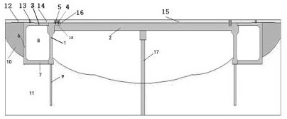
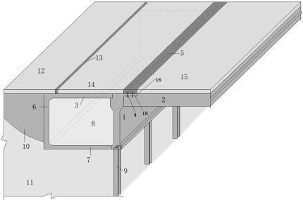
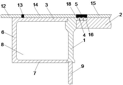
[0023] The fabricated steel abutment of the present invention comprises a main girder 2 and a bridge deck 15 arranged on the main girder 2. H-shaped steel piles 9 are embedded in the soil below the two ends of the main girder 2. In the width direction of 2, 3-4 groups of H-shaped steel piles 9 are arranged at intervals, and a steel flexible abutment 1 is fixed above the H-shaped steel piles 9. The steel flexible abutment 1 is a steel part made by precasting, A steel ground beam 7 is horizontally fixed on the rear side of the lower platform of the steel flexible abutment 1, and a steel secondary abutment 6 is vertically fixed on the rear end of the steel ground beam 7. The steel flexible abutment 1 A steel roof girder 3 is horizontally fixed between the steel se...


PUM


Abstract

The invention relates to an assembly type mouth-shaped framework steel bridge abutment and a construction method thereof. The assembly type mouth-shaped framework steel bridge abutment comprises a main beam and a bridge panel arranged on the upper surface of the main beam, wherein H-shaped steel piles are embedded into soil layers below the two ends of the main beam; a steel flexible bridge abutment is fixedly arranged above the H-shaped steel pilers; a steel ground beam is horizontally fixed at the rear side of a lower table of the steel flexible bridge abutment; a steel secondary bridge abutment is vertically fixed at the rear end of the steel ground beam; a steel top beam is horizontally fixed between the steel flexible bridge abutment and the steel secondary steel abutment; one side, away from the steel top beam, of the steel flexible bridge abutment is fixedly connected to the main beam; the steel flexible bridge abutment, the steel ground beam, the steel secondary bridge abutmentand the steel top beam define a mouth-shaped framework; and an EPS elastic material is filled in the mouth-shaped framework. The assembly type mouth-shaped framework steel bridge abutment is good inintegral deformation performance, is suitable for a strong earthquake area, and can reduce unstable travelling phenomena caused by bumping at a bridge head.

Description

Technical field: [0001] The invention relates to the fields of bridge engineering, pile foundation engineering and the like, in particular to an assembled type square frame steel abutment and a construction method thereof. Background technique: [0002] In traditional bridges, the temperature expansion and contraction deformation of the main girder in the longitudinal bridge direction is not constrained by the abutment, and the earth pressure on the abutment is not transmitted to the main girder. Due to the problem of vehicle jumping behind the abutment, the telescopic device at the pier is more likely to cause disease than the telescopic device at the pier; in addition, modern bridges adopt more continuous structures so that the telescopic device at the pier is canceled, which makes the telescopic device at the abutment cancelled. Devices are gaining more and more attention. [0003] Although the integral bridge eliminates the expansion joints in structure, it has many adv...

Claims


Application Information

Patent Timeline
Patent Type & Authority Applications(China)
IPC IPC(8): E01D19/02E01D101/30E01D101/40
CPCE01D19/02E01D2101/30E01D2101/40
Inventor 黄福云桂奎单玉麟刘征峰何凌峰
Owner FUZHOU UNIV
Why Eureka
Try Eureka