Spatial orientation method and device based on binocular camera

A binocular camera and spatial positioning technology, which is applied in image analysis, image enhancement, instruments, etc., can solve the problems of small moving range, poor system stability, and high cost, and achieve the effect of avoiding small moving range and reducing costs

Active Publication Date: 2018-02-16
GOERTEK INC
View PDF3 Cites 23 Cited by
  • Summary
  • Abstract
  • Description
  • Claims
  • Application Information

AI Technical Summary

Problems solved by technology

[0004] It can be seen that the VR spatial positioning technology in the prior art has

Method used


Image

  • Spatial orientation method and device based on binocular camera
  • Spatial orientation method and device based on binocular camera
  • Spatial orientation method and device based on binocular camera

Examples


Embodiment Construction

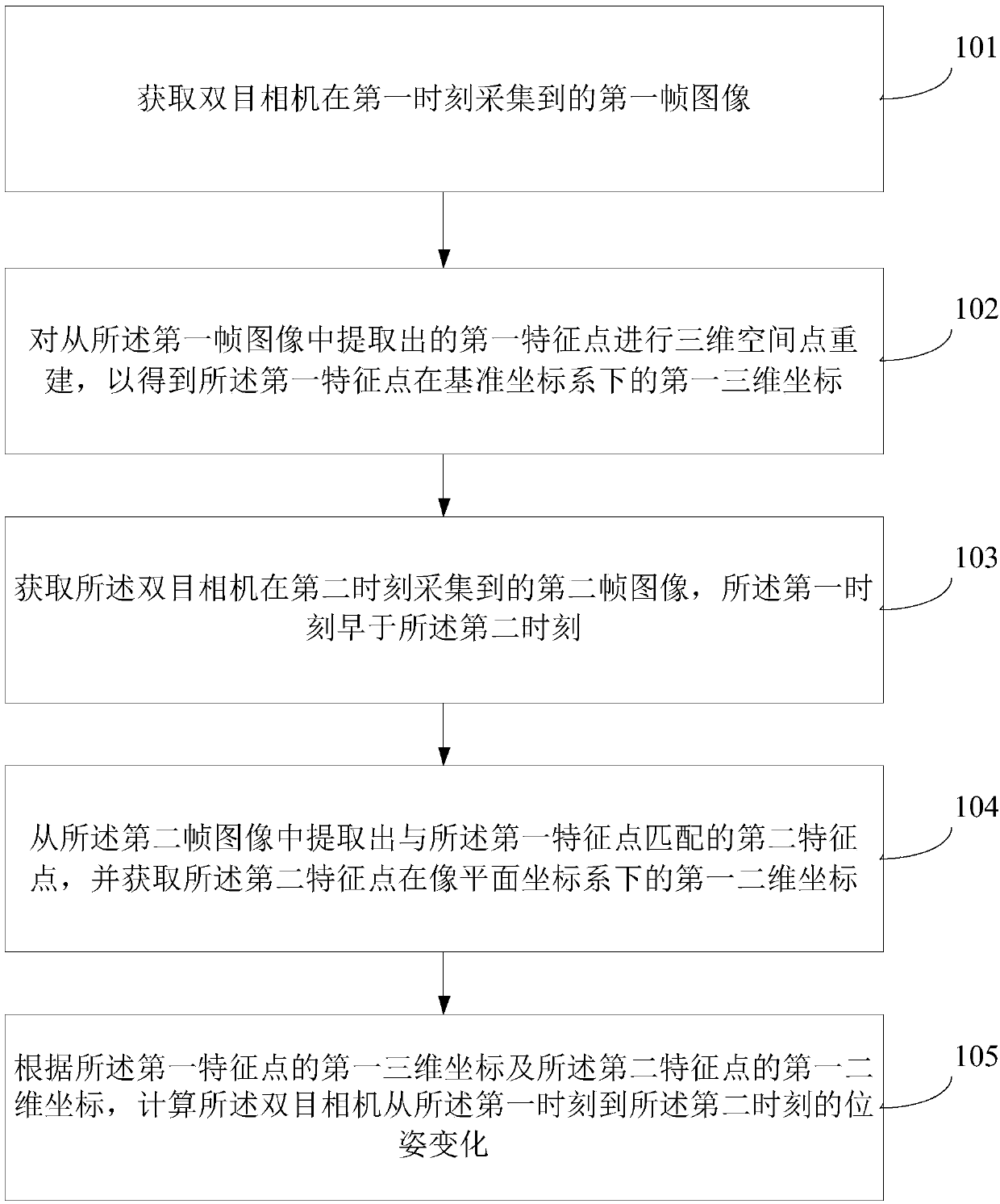
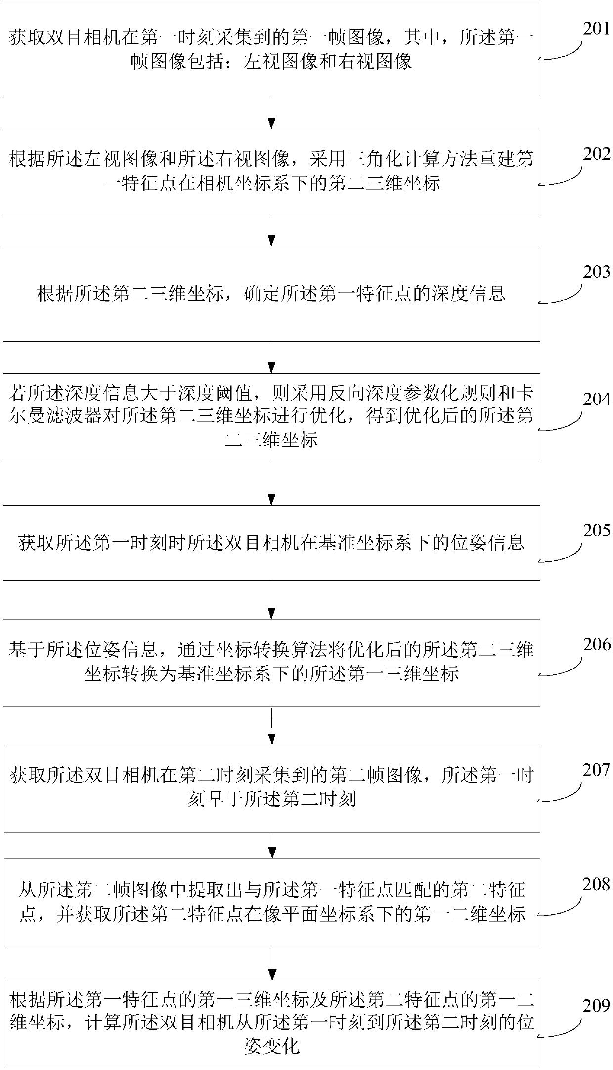
[0020] In order to make the purpose, technical solutions and advantages of the embodiments of the present invention clearer, the technical solutions in the embodiments of the present invention will be clearly and completely described below in conjunction with the drawings in the embodiments of the present invention. Obviously, the described embodiments It is a part of embodiments of the present invention, but not all embodiments. Based on the embodiments of the present invention, all other embodiments obtained by persons of ordinary skill in the art without making creative efforts belong to the protection scope of the present invention.

[0021] Terms used in the embodiments of the present invention are only for the purpose of describing specific embodiments, and are not intended to limit the present invention. The singular forms "a", "said" and "the" used in the embodiments of the present invention and the appended claims are also intended to include plural forms, unless the ...


PUM


Abstract

The invention discloses a spatial orientation method and device based on a binocular camera. The method includes the steps of acquiring a first frame image collected by a binocular camera at a first moment; performing three-dimensional space point reconstruction on a first feature point extracted from the first frame image to obtain first three-dimensional coordinates of the first feature point ina reference coordinate system; acquiring a second frame image collected by the binocular camera at a second moment, the first moment being earlier than the second moment; extracting a second featurepoint that matches the first feature point in the second frame image and acquiring first two-dimensional coordinates of the second feature point in an image plane coordinate system; and calculating, according to the first three-dimensional coordinates of the first feature point and the first two-dimensional coordinates of the second feature point, a posture change of the binocular camera from thefirst moment to the second moment. The embodiments of the invention can reduce the manufacturing cost and increase the supportable moving range.

Description

technical field [0001] The present invention relates to the technical field of positioning, in particular to a spatial positioning method and device based on a binocular camera. Background technique [0002] At present, virtual reality (Virtual Reality, VR for short) technology is more and more applied in real life, so that users can be immersed in the virtual world. [0003] The existing VR spatial positioning technology mainly relies on external laser towers to scan the calibration points on the virtual reality device to achieve spatial positioning. However, due to the need for an external positioning device (laser tower), the effectively used space in the virtual reality device is limited (usually 5m×5m) and the cost is high. At the same time, when the positioning device is accidentally touched during use to change its position, the entire positioning system needs to be re-initialized according to the new position. [0004] It can be seen that the VR spatial positioning...

Claims


Application Information

Patent Timeline
IPC IPC(8): G06T7/73G06T7/55
CPCG06T2207/10016G06T7/55G06T7/73
Inventor 李舜铭戴天荣任玉川曹进喜宋浩冉
Owner GOERTEK INC
Why Eureka
Try Eureka