A reconfigurable antenna

A technology for reconstructing antennas and antennas, which is applied to the connection of antennas, antenna grounding switch structures, and the combination of antenna units with different polarization directions. Construct and achieve the effect of refactoring

Active Publication Date: 2021-01-01
YUNAN JINGCHUANG LIQUID METAL THERMAL CONTROL TECH RES & DEV CO LTD
View PDF8 Cites 0 Cited by
  • Summary
  • Abstract
  • Description
  • Claims
  • Application Information

AI Technical Summary

Problems solved by technology

[0005] The technical problem to be solved by the present invention is to solve the problem that the existing solid metal antenna has a single structure and is difficult to meet the application requirements in various environments

Method used


Image

  • A reconfigurable antenna
  • A reconfigurable antenna
  • A reconfigurable antenna

Examples


Embodiment 1

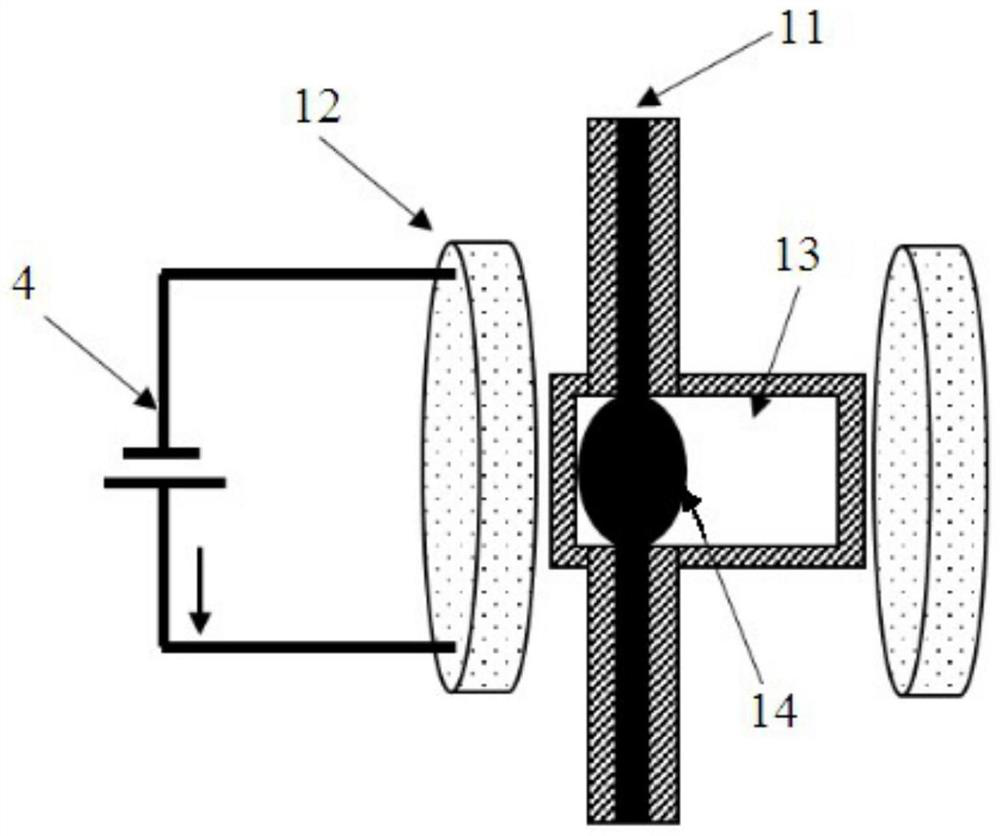
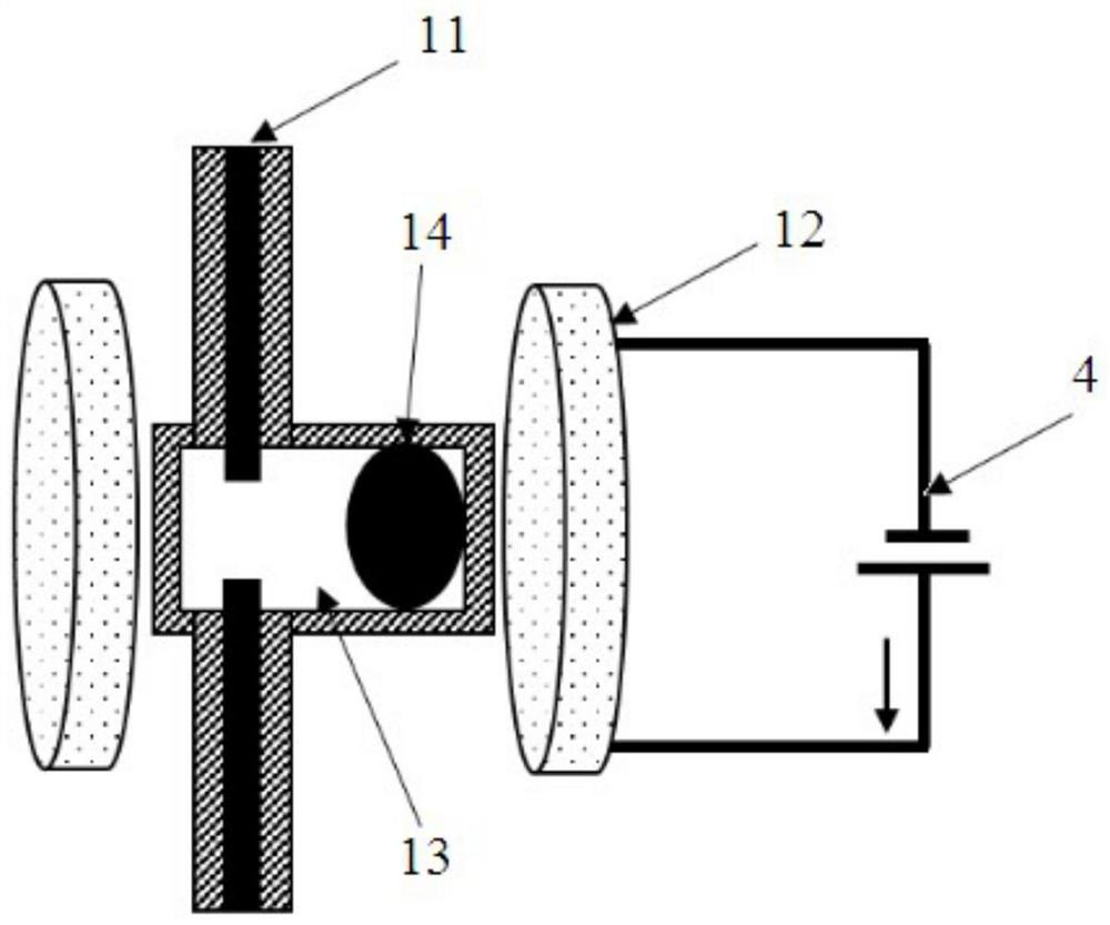
[0027] like figure 1 , figure 2 and image 3 As shown, the reconfigurable antenna provided by the embodiment of the present invention includes a plurality of antenna assemblies 1, the antenna assembly 1 includes an antenna body 11, a reconfiguration magnet and two electromagnets 12, and the reconfiguration magnet includes a chamber 13 and a magnetic body 14 , the magnetic body 14 is located in the chamber 13, the antenna body 11 passes through the chamber 13 from the outside, and the antenna body 11 is disconnected in the chamber 13, two electromagnets 12 are respectively located on both sides of the chamber 13, and the electromagnet The installation direction of 12 is perpendicular to the installation direction of the antenna body 11.

[0028] The reconfigurable antenna of the present invention first places a specific magnetic body in the cavity, and the cavity is located in the magnetic field formed by an external electromagnet. The movement of the magnetic body in the ca...

Embodiment 2

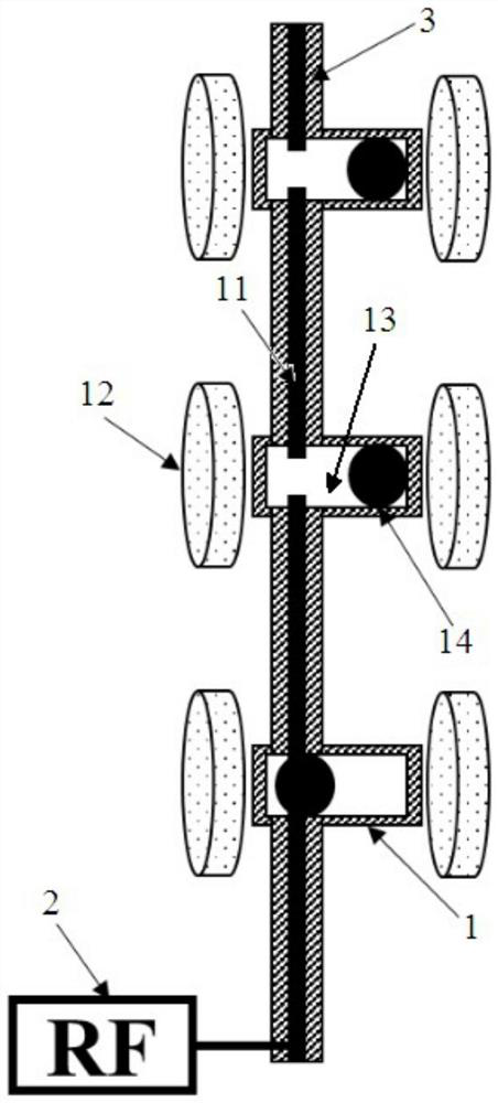
[0037] like Figure 4 As shown, the reconfigurable antenna provided in Embodiment 2 of the present invention is basically the same as the reconfigurable antenna in Embodiment 1, the difference is that in this embodiment, multiple antenna components 1 are connected in parallel, and the head end and tail end of each antenna body 11 The ends are connected separately. The antenna components are arranged at equal intervals, and the head end of the antenna body is connected to the main circuit, and the tail end is connected to the radio wave generator. Under the control of the external magnetic field generated by the energization of the electromagnet, the magnetic body in the chamber connects the antenna body and the radio wave generator to short-circuit the lower section of the antenna, thereby changing the length of the antenna.

[0038]To sum up, the reconfigurable antenna of the present invention first places a specific magnetic ball in the cavity, and the cavity is located in ...


PUM


Abstract

The invention relates to the technical field of antennas, in particular to a reconfigurable antenna. The reconfigurable antenna comprises a plurality of antenna modules, wherein each antenna module comprises an antenna, a reconfiguration magnet and two electromagnets, the reconfiguration magnet comprises a cavity and a magnetic body, the magnetic body is arranged in the cavity, the antenna penetrates through the cavity from outside and is broken in the cavity, the two electromagnets are respectively arranged at two sides of the cavity, and the arrangement direction of the electromagnets is perpendicular to the arrangement direction of the antenna. The special magnetic body is arranged in the cavity, the cavity is arranged in a magnetic field formed by external electromagnets, the motion ofthe magnetic body in the cavity is controlled by an external magnetic field, and the position where the magnetic body is located is charged; and the antenna penetrates through the cavity from the outside, is broken to from an opening and then penetrates out of the cavity, the two electromagnets are respectively energized, the magnetic body can move around a position of the opening of the antennain the cavity in a reciprocating way to achieve connection and disconnection of the antenna, the reconfiguration of the length and the shape of the antenna is conveniently and effectively achieved, and the requirements of the antenna in different environments and application states are met.

Description

technical field [0001] The present invention relates to the technical field of antennas, in particular to a reconfigurable antenna. Background technique [0002] An antenna is a device used in radio equipment to transmit or receive electromagnetic waves. Engineering systems such as radio communication, broadcasting, television, radar, navigation, remote sensing, and radio astronomy, which use electromagnetic waves to transmit information, rely on antennas to work. In recent years, with the rapid development of radar and communication systems, antennas of various sizes and shapes are required for automobiles, aircraft, ships and various civilian electronic equipment. The traditional solid metal antenna only has a specific shape, and in order to meet the requirements of different radio signal transmission and reception, it can only be solved by carrying multiple antennas, which undoubtedly increases the production cost and space occupied by the antenna. [0003] The shape an...

Claims


Application Information

Patent Timeline
Patent Type & Authority Patents(China)
IPC IPC(8): H01Q1/42H01Q1/50H01Q21/24H01Q23/00
CPCH01Q1/42H01Q1/50H01Q21/24H01Q23/00
Inventor 国瑞盛磊刘静
Owner YUNAN JINGCHUANG LIQUID METAL THERMAL CONTROL TECH RES & DEV CO LTD
Why Eureka
Try Eureka