
Relay unit and application system thereof

A technology of relay unit and control unit, which is applied in the direction of data exchange details, line transmission components, data switch current source, etc., and can solve the problems affecting the communication of existing equipment, many cable cascading fault points, and heavy field wiring workload, etc. problems, to achieve communication availability and reliability, to solve the shortening of signal transmission distance, and to improve the effect of signal anti-interference ability

Pending Publication Date: 2020-06-19
XIANGJIANG TECH
View PDF0 Cites 0 Cited by
  • Summary
  • Abstract
  • Description
  • Claims
  • Application Information

AI Technical Summary

Problems solved by technology

The disadvantages of using cable connection are: heavy on-site wiring workload; many cable cascading failure points; adding equipment requires changing cables, which affects the communication of existing equipment; not beautiful enough

Method used


Image

  • Relay unit and application system thereof
  • Relay unit and application system thereof
  • Relay unit and application system thereof

Examples


Embodiment 1

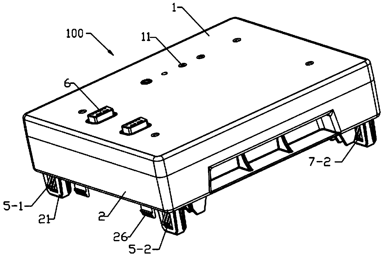
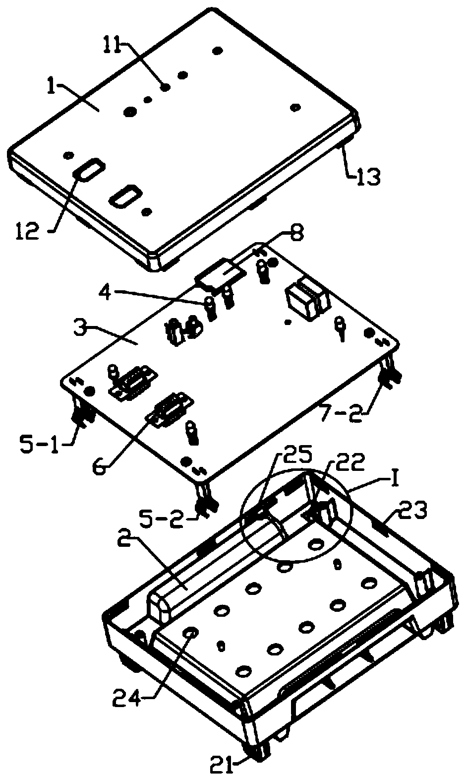
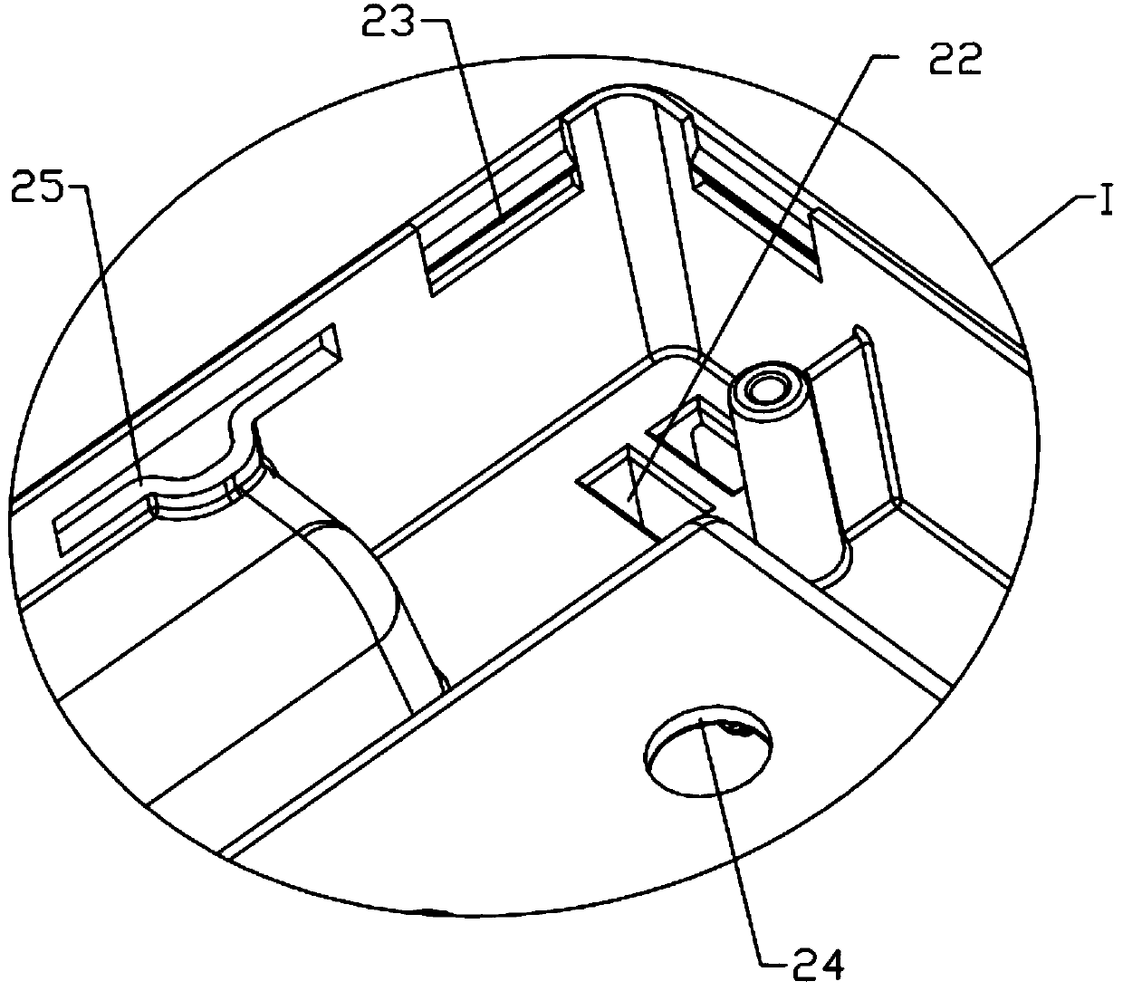
[0030] Relay unit 100, see Figure 1 to Figure 5 , including a shell and a control unit, the control unit is installed in the shell, the control unit includes a circuit board 3, a low-voltage DC power adapter module, a communication adapter module and a sensor module, a low-voltage DC power adapter module, a communication adapter module and The sensing modules are all connected to the circuit board 3 . The low-voltage DC power adapter module includes low-voltage DC power supply bus reed sets 5-1 and 5-2; the communication adapter module includes communication bus reed sets 7-1 and 7-2.

[0031] In this example, there are two low-voltage DC power supply bus reed sets, which are low-voltage DC power supply bus reed sets 5-1 and 5-2, and the low-voltage DC power supply bus reed sets 5-1 and 5-2 are respectively connected to two sections The low-voltage DC power bus of the composite bus is connected to a PCB board (ie, a circuit board). The circuit board can be provided with rela...

Embodiment 2

[0044] A kind of relay unit application system, see Image 6 , comprising the relay unit 100 described in Embodiment 1, and further comprising a busbar, a busbar 300 and a power module 400, the busbar is arranged in the busbar 300, and the busbar includes a power supply busbar, a low-voltage DC power supply busbar and a communication busbar, Both the relay unit and the power module 400 are directly or indirectly arranged on the bus duct 300 . The bus ducts 300 are connected through the end cover 200 , and the relay unit 100 may be disposed on the end cover 200 .


PUM


Abstract

The invention discloses a relay unit and an application system thereof, wherein the relay unit comprises a shell and a control unit, the control unit is installed in the shell, the control unit comprises a circuit board, a low-voltage direct-current power supply switching module, a communication switching module and a sensing module, and the low-voltage direct-current power supply switching module, the communication switching module and the sensing module are all connected to the circuit board. The relay unit disclosed by the invention adopts the low-voltage direct-current power supply switching module and the communication switching module to realize the cascade connection of the low-voltage direct-current power supply bus and the communication bus, and the relay unit realizes the connection or disconnection of the low-voltage direct-current power supply bus and the relay or disconnection function of the communication bus according to the operation requirements of the system. The relay unit is also integrated with a sensing module and can be used for a power supply bus contact temperature monitoring function, a bus shell temperature detection function, an environment temperature and humidity monitoring function, a vibration detection function, a communication port expansion function and the like.

Description

technical field [0001] The invention relates to electrical connection technology, in particular to a relay unit and its application system. Background technique [0002] The terminal bus bar is usually a terminal power distribution device composed of copper conductors and aluminum alloy shells. Through the matching plug-in boxes and other devices, it can realize the function of supplying power to specific equipment. Especially in the power supply of the network cabinet in the data center, the power supply mode of the terminal bus has increasingly replaced the traditional cable power supply mode of the head cabinet. This power supply mode can provide a large power output capability and has a strong expansion capacity, and at the same time, it saves precious space resources after replacing the top cabinets, enabling users to deploy more network cabinets. It has also become a trend to adopt the terminal bus power supply method in the construction of data centers. The terminal...

Claims


Application Information

Patent Timeline
Patent Type & Authority Applications(China)
IPC IPC(8): H04B3/36H04L12/10
CPCH04B3/36H04L12/10
Inventor 王志远黄欢欧荣辉
Owner XIANGJIANG TECH
Learn More