

Fuel injection control device
A control device and fuel injection technology, which is applied in fuel injection control, electrical control, engine control, etc., can solve the problems of obtaining the valve opening period, unable to detect the valve opening delay time, etc., and achieve the effect of improving the accuracy of injection quantity
- Summary
- Abstract
- Description
- Claims
- Application Information
AI Technical Summary
Problems solved by technology
Method used
Image

Examples
no. 1 Embodiment approach
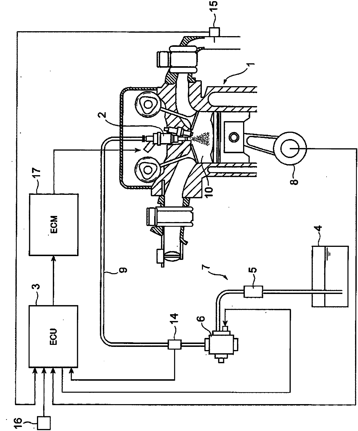
[0029] figure 1 It is a diagram showing a schematic configuration of an internal combustion engine system to which the first embodiment of the fuel injection control device according to the present invention is applied.
[0030] As shown in the figure, this system is mainly composed of an internal combustion engine (hereinafter referred to as the engine) 1, a fuel supply device 7, an engine control module (ECM) 17 for driving the fuel injection valve 2 of the engine 1, an engine control unit (ECU) (fuel Injection control device) 3 constitutes. The fuel supply device 7 supplies fuel from the fuel tank 4 to the fuel injection valve 2 provided in the engine 1 through the fuel pipe 9, and injects a predetermined amount of fuel from the fuel injection valve 2 into the combustion chamber 10. The low-pressure fuel pump 5 is pressurized once, adjusted to a certain pressure by a fuel pressure regulator not shown, and pressurized to a higher pressure secondarily by the high-pressure fu...
no. 2 Embodiment approach
[0098] This second embodiment is a modified form based on the first embodiment, and is the same as the first embodiment except for the following description.
[0099] In the above-mentioned first embodiment, in the cycle of the engine 1 that satisfies the learning condition, one fuel injection is divided into multiple times, and the injection amount ratio of any one or multiple times of them is different in multiple cycles (in the example shown in the figure). 3 cycles), and the injection pulse width (divided injection pulse width) in which the fuel injection valve 2 is controlled to be in the middle lift state is taken as the horizontal axis, and the corresponding valve closing delay time is taken as On the vertical axis, a linear approximation formula is obtained from this, and the valve opening delay time is estimated using the linear approximation formula.
[0100] Alternatively, the injection pulse width of one cycle may be divided into a plurality of times, and the injec...
no. 3 Embodiment approach
[0104] This embodiment is a modified form based on the first embodiment or the second embodiment, and is the same as the first embodiment or the second embodiment except for the following description.
[0105] In the above-mentioned second embodiment, the injection pulse width of one cycle is divided into a plurality of times, and the injection amount ratio of any one of them is changed in at least two consecutive cycles.
[0106] On the other hand, it is also possible to change the injection amount ratio once in two discontinuous cycles.
[0107] Figure 12 It is a diagram showing an example of a determination procedure of the injection pulse width Ti in the third embodiment of the fuel injection control device according to the present invention. In this third embodiment, the injection amount ratio from the first cycle to the third cycle is not changed, and the injection amount ratio is changed arbitrarily from the fourth cycle. The ratio of the injection amount of the 4 cy...
PUM
 Abstract
Description
Claims
Application Information