Fuel injector

A fuel injection valve and valve body technology, which can be applied to fuel injection devices, special fuel injection devices, and fuel injection devices with measures to reduce wear, etc., can solve problems such as long time, improve accuracy, and prevent reduction of flow path area. , The effect of shortening the valve closing delay time

Inactive Publication Date: 2013-04-03
HITACHI AUTOMOTIVE SYST LTD
View PDF6 Cites 6 Cited by
  • Summary
  • Abstract
  • Description
  • Claims
  • Application Information

AI Technical Summary

Problems solved by technology

[0006] In the fuel injection valve constructed in this way, there is a problem that the collision surface between the end surface of the armature and the end surface of the fixed core adheres to each other, and after the magnetic force of the magnetic circuit disappears, until the armature returns to the original position, that is, the two are completely separated. It takes a long time until the valve body is pressed against the seat

Method used


Image

  • Fuel injector
  • Fuel injector
  • Fuel injector

Examples


Embodiment Construction

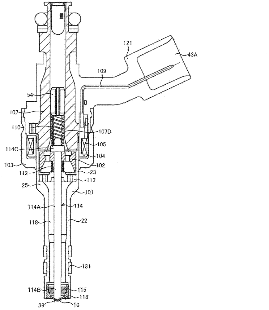
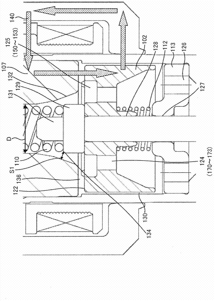
[0066] Below, use Figure 1 to Figure 7 , illustrating the structure of an embodiment of the fuel injection valve of the present invention. figure 1 is a longitudinal sectional view of the fuel injection valve in this embodiment. figure 2 yes figure 1 Partially enlarged view of , showing details of the fuel injection valve in this embodiment.

[0067] The nozzle holder 101 includes a small-diameter cylindrical portion 22 with a small diameter and a large-diameter cylindrical portion 23 with a large diameter. Into the interior of the front end portion of the small-diameter cylindrical portion 22, the guide member 115 and the orifice cup (orifice cup) 116 provided with the fuel injection port 10 are stacked and inserted in this order. The outer peripheral portion of the front end surface is fixed to the small-diameter cylindrical portion 22 by welding. The guide member 115 guides the outer periphery of a valve body 114B provided at the tip of a plunger rod 114A constituting...


PUM


Abstract

The invention provides a fuel injector. To improve the injection fuel mass accuracy of a fuel injector, it is necessary to make the fuel injector perform seat valve (114B) opening and closing operation quickly. When the shapes of a fixed core (107) and an anchor (102) are optimized to improve the responsiveness of a magnetic flux, it is necessary to ensure a sufficient fuel path area while preventing adhesion by making the adherence phenomenon rarely occur between an end face of the anchor (102) and an end face of the fixed core (107). To achieve the above object, in the invention, a through hole passing through an anchor (102) forming an armature (114) of an electromagnetic fuel injector from a face of the anchor (102) facing a fixed core (107) to a back face is formed so that the through hole has a large-diameter portion (125) and a small-diameter portion (124), wherein the large-diameter portion (125), relative to the small-diameter portion (124), is located at the upstream side and shifts to an outer circumferential side.

Description

technical field [0001] The present invention relates to a fuel injection valve used in an internal combustion engine, in particular to a fuel injection valve that opens and closes a fuel passage through an electromagnetically driven movable member. Background technique [0002] An internal combustion engine is provided with a fuel injection control device for converting an appropriate fuel amount according to an operating state into an injection timing of a fuel injection valve, and driving a fuel injection valve for supplying fuel. In the fuel injection valve, a valve body constituting the fuel injection valve is opened and closed by a magnetic force generated by an electric current flowing through an internal solenoid, and fuel is injected. The amount of injected fuel is mainly determined by the pressure difference between the pressure of the fuel and the atmospheric pressure at the nozzle portion of the fuel injection valve, and the timing of maintaining the valve body in...

Claims


Application Information

Patent Timeline
Patent Type & Authority Applications(China)
IPC IPC(8): F02M51/06F02M61/18
CPCF02M2200/02F02M51/0664F02M2200/08F02M2200/07F02M51/0671
Inventor 三宅威生草壁亮安部元幸相马正浩
Owner HITACHI AUTOMOTIVE SYST LTD
Why Eureka
Try Eureka