Pressure accumulation fuel injection controller

一种燃料喷射、燃料喷射阀的技术,应用在燃料喷射控制、燃料喷射装置、电气控制等方向,能够解决发动机燃烧不稳、不稳、发动机性能变化等问题

Inactive Publication Date: 2007-01-24
DENSO CORP
View PDF1 Cites 7 Cited by
  • Summary
  • Abstract
  • Description
  • Claims
  • Application Information

AI Technical Summary

Problems solved by technology

However, the fuel injection device does not always control the pressure relief valve
Thus, the problems of unstable engine combustion and variable or unstable engine performance still exist

Method used


Image

  • Pressure accumulation fuel injection controller
  • Pressure accumulation fuel injection controller
  • Pressure accumulation fuel injection controller

Examples


Embodiment Construction

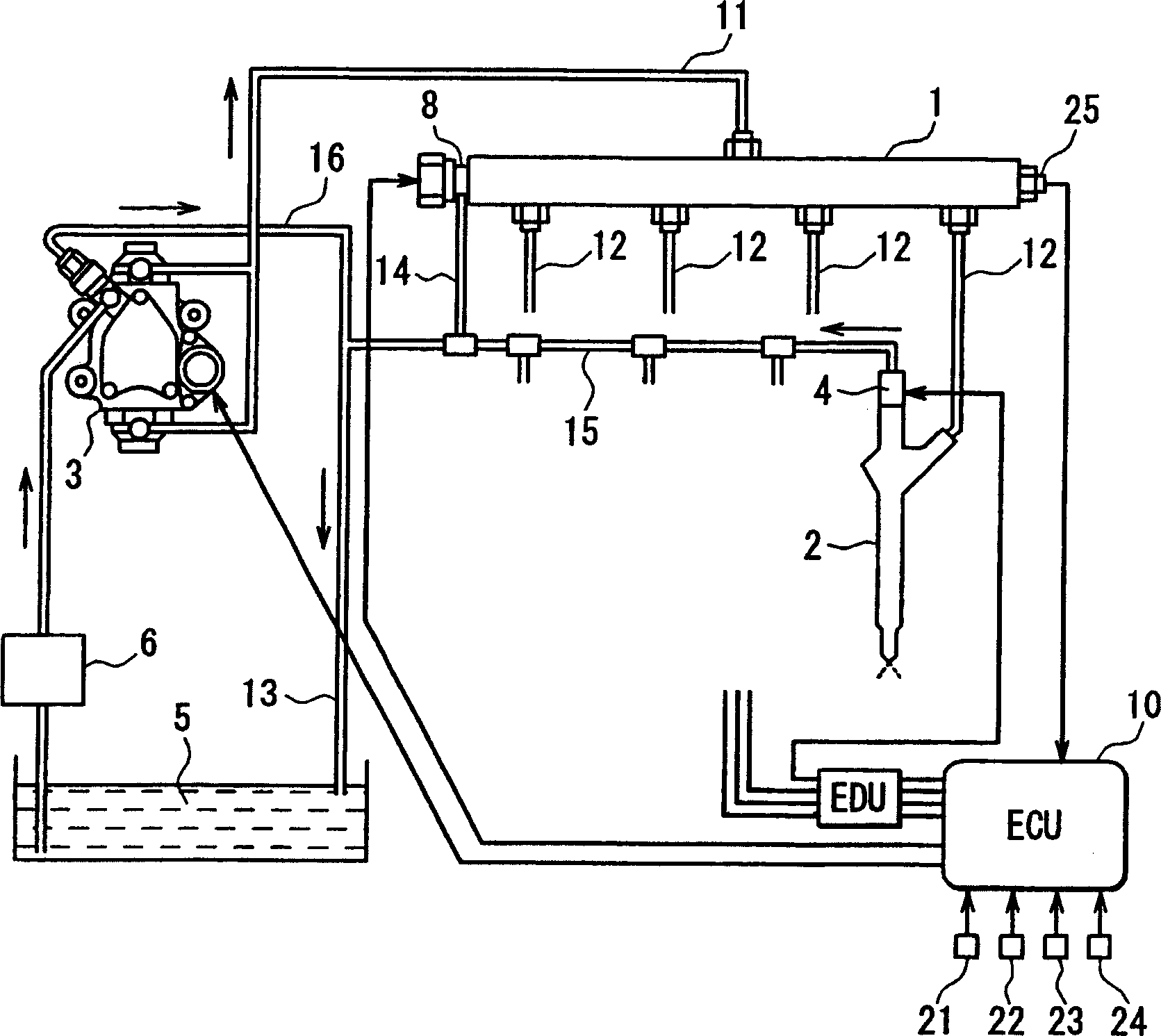
[0014] see figure 1 , which shows an accumulator type fuel injection controller according to an exemplary embodiment of the present invention. This fuel injection controller has a pressure accumulation container 1 (common rail), a plurality (four in the present embodiment) of fuel injection valves (injectors) 2, a fuel supply pump (delivery pump) 3, and an electronic control unit ( ECU) 10. The common rail 1 provides an accumulator for accumulating high-pressure fuel corresponding to the fuel injection pressure. A plurality of injectors 2 are connected to the common rail 1, and inject fuel into each cylinder of a four-cylinder engine, where the four-cylinder engine is, for example, a multi-cylinder diesel engine. The supply pump 3 is driven to rotate by the engine. The ECU 10 functions as a control section for performing electronic control on the plurality of injectors 2 and the charge pump 3 .

[0015] The common rail 1 needs to continuously store high-pressure fuel corre...


PUM


Abstract

A pressure pattern estimation device of a fuel injection controller of an engine estimates a pressure transition of fuel in a common rail. A surplus pressure range calculation device of the fuel injection controller calculates a surplus pressure range in which pressure pattern data provided by the pressure pattern estimation device exceeds a target common rail pressure. The fuel injection controller releases the common rail pressure to a lower-pressure side by operating a pressure reduction valve of the common rail to eliminate the surplus pressure range calculated by the surplus pressure range calculation device. Thus, the common rail pressure (injection pressure) during an injection period is smoothed.

Description

technical field [0001] The present invention relates to an accumulator type fuel injection controller, which is mainly used in diesel engines. Background technique [0002] It is known to use an accumulator-type fuel injection device as a fuel injection device for a diesel engine, which has an accumulator container (common rail), fuel injection valves (injectors) and a suction fuel metering pump. High-pressure fuel that matches the fuel injection pressure is stored in the pressure accumulation container. The injector injects high-pressure fuel in an accumulator tank and delivers it to each cylinder of the engine. The supply pump pressurizes the fuel sucked into the pressurization chamber to a high pressure, and performs pressure delivery of the fuel to deliver it into the pressure accumulation container. [0003] For ordinary accumulator type fuel injection devices, the rail pressure in the accumulator container is always fluctuating according to the waveform because the r...

Claims


Application Information

Patent Timeline
Patent Type & Authority Applications(China)
IPC IPC(8): F02D41/38F02M47/00
CPCF02M63/025F02M47/027F02D2200/0604F02M63/0225F02M63/04F02D41/3845F02D2200/0602F02D2041/2027
Inventor 中根伦明
Owner DENSO CORP
Why Eureka
Try Eureka