Local cooling metal mold with stable side edge

A local cooling and metal mold technology, applied in the direction of metal processing equipment, forming tools, manufacturing tools, etc., can solve the problems of increasing the production and operation costs of enterprises, mold bumps, and large water consumption, so as to avoid excessive temperature rise and increase Temperature controllability, effect of prolonging thermal interaction time

Inactive Publication Date: 2018-02-23
湖州练市培峰金属制品厂
View PDF0 Cites 0 Cited by
  • Summary
  • Abstract
  • Description
  • Claims
  • Application Information

AI Technical Summary

Problems solved by technology

[0007] There is still a problem when the mold is heated. The high-temperature heating medium such as high-temperature liquid or high-temperature gas will produce certain vibrations. These vibrations will cause bumps to the mold and affect the molding effect. Defective products, therefore, increasing the positioning stability of the mold under high temperature environment is also the research direction of mold design
[0008] In the actual production process, in addition to the need to heat the mold in advance, it is also necessary to cool the mold in the subsequent process. The existing cooling treatment often uses water cooling to cool the entire mold, but there are three cooling methods: Disadvantages: First, it needs to consume a lot of water resources, and the non-environmental protection also increases the production and operation costs of the enterprise; secondly, the mold needs to be heated up rapidly after cooling down, and a large-scale overall cooling of the entire mold often leads to excessive cooling. , so that the subsequent re-heating has an adverse effect; finally, for the overall cooling of the mold, the mold is frequently heated and cooled multiple times within a day, which is easy to cause damage and deformation to the mold body.

Method used


Image

  • Local cooling metal mold with stable side edge
  • Local cooling metal mold with stable side edge
  • Local cooling metal mold with stable side edge

Examples


Embodiment 1

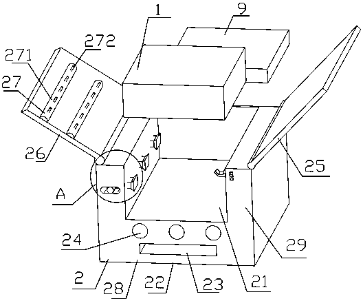
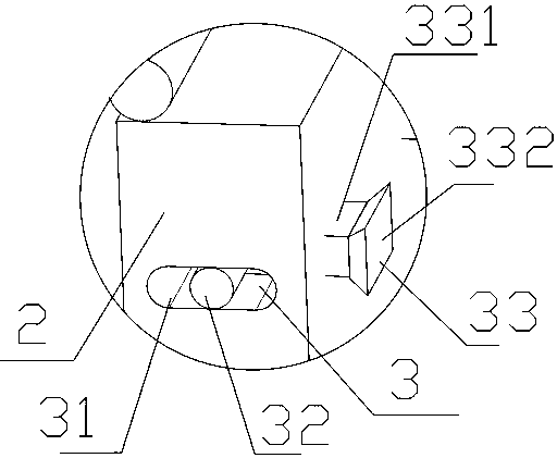
[0055] Example 1, such as figure 1 with figure 2 Shown: a locally cooled metal mold with stable sides, including a mold body 1 and a heating device 2 for heating the mold body 1. The heating device 2 is provided with a cavity 21 for accommodating the mold body 1, and the heating device 2 includes There are a main body 28 and two lateral extensions 29 extending in the vertical direction on both sides of the main body 28. The two lateral extensions 29 are respectively hinged with a hinge plate 25 and a hinge plate 26, and a hinge plate 25 Both the hinge plate 2 and the hinge plate 2 can be turned over to cover the accommodating cavity 21; the main body 28 contains a constant temperature heating part 22, and the constant temperature heating part 22 is provided with a main heating plate inlet 23 and a secondary pipe inlet 24; hinge plate two 26 is provided with spot heating 装置27。 Device 27.

[0056] During production and processing, the mold body 1 is placed in the accommodating cavi...


PUM


Abstract

The invention relates to the field of industrial product molding, in particular to a locally cooled metal mold with stable sides. A side-stabilized local cooling metal mold, comprising a mold body and a heating device for heating the mold body, the heating device is equipped with a tool that can slide in the horizontal direction and is used to insert into the side of the mold body Side fixing device, the side fixing device includes an operating shaft for operation, a heat insulating block for heat insulation, and a protruding part at the end of the operating shaft for inserting into the mold body, the protruding The part includes an intrusion cone and an anti-locking piece arranged on the intrusion cone. The purpose of the present invention is to provide a metal mold with stable side and local cooling, which includes a side fixing device, which locks the mold from the side, increases the positioning stability of the mold in a high temperature environment, and also adds a local cooling device, which can effectively shape the mold The temperature of the area is quickly and slightly lowered, the speed is fast, and the damage to the mold is small.

Description

Technical field [0001] The invention relates to the field of industrial product molding, in particular to a local cooling metal mold with stable sides. Background technique [0002] Molds, various molds and tools used in industrial production to obtain desired products by injection molding, blow molding, extrusion, die-casting or forging molding, smelting, and stamping. A mold is a tool used to shape objects. This tool is composed of various parts, and different molds are composed of different parts. It mainly realizes the processing of the shape of the article by changing the physical state of the formed material. Under the action of external force, the blank becomes a tool with a specific shape and size. It is widely used in punching, die forging, cold heading, extrusion, powder metallurgy parts pressing, pressure casting, and compression molding or injection molding of engineering plastics, rubber, ceramics and other products. The mold has a specific contour or inner cavity...

Claims


Application Information

Patent Timeline
Patent Type & Authority Applications(China)
IPC IPC(8): B21D37/16B21D37/10
CPCB21D37/16B21D37/10
Inventor 谢鑫峰
Owner 湖州练市培峰金属制品厂
Why Eureka
Try Eureka