
Portable household electric drill

A household electric drill, portable technology, applied in portable drilling rigs, drilling/drilling equipment, metal processing equipment, etc., can solve the problems of unsafe workers, difficult cleaning work, flying dust and debris, etc., to achieve Reasonable storage or installation, improved drilling efficiency, simple and uncomplicated structure

Inactive Publication Date: 2018-02-23
徐应盈
View PDF11 Cites 1 Cited by
  • Summary
  • Abstract
  • Description
  • Claims
  • Application Information

AI Technical Summary

Problems solved by technology

[0003] Due to the ventilation and heat dissipation of the electric drill, there is a lot of dust inside after long-term use. The dust will mix and deteriorate the lubricating oil on the gears and bearings and dry up, which will aggravate wear and tear, especially if it is used in an alternative way. There is an excessively large gap, so it is extremely necessary to keep the interior clean. At the same time, due to the large amount of dust generated during work, the cleaning work is difficult to complete. At the same time, although the staff will wear a protective cover to work, it will affect the surrounding environment. Dust and Debris will fly randomly, causing serious pollution;
[0004] When using an electric drill, it is often necessary to replace the drill bit. Because of the convenience, the operator directly replaces the drill bit when the electric drill is not powered off. If you or someone else accidentally touches the switch when changing the drill bit, it is very dangerous. At present, when the household electric drills used in the market need to drill to the top, the electric drill body can only be turned upwards. On the one hand, it affects the accuracy, on the other hand, there is no guarantee for the safety of the staff, it is inconvenient to use, and there are some problems in positioning during the work process. lacking

Method used


Image

  • Portable household electric drill
  • Portable household electric drill
  • Portable household electric drill

Examples


Embodiment Construction

[0027] In order to deepen the understanding of the present invention, the present invention will be further described below in conjunction with the accompanying drawings. This embodiment is only used to explain the present invention, and does not constitute a limitation to the protection scope of the present invention.

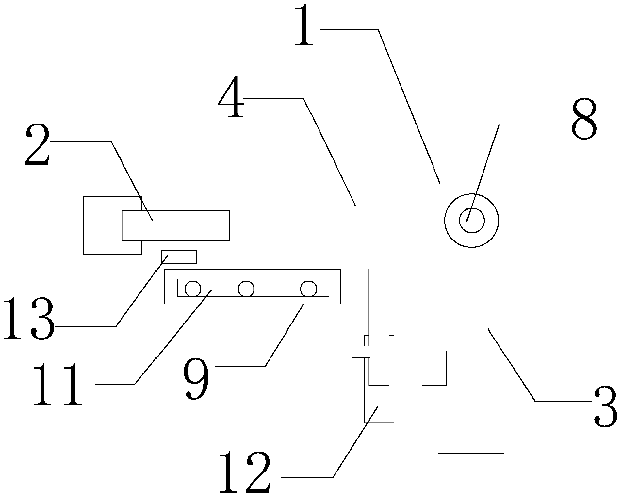
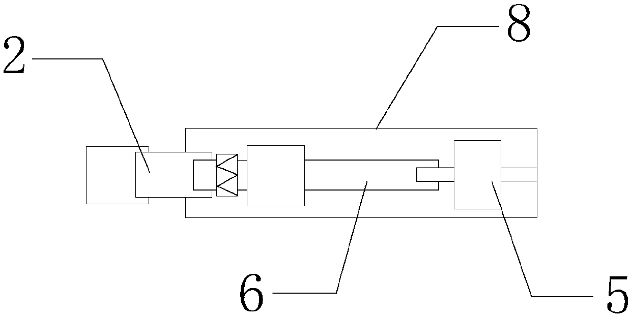
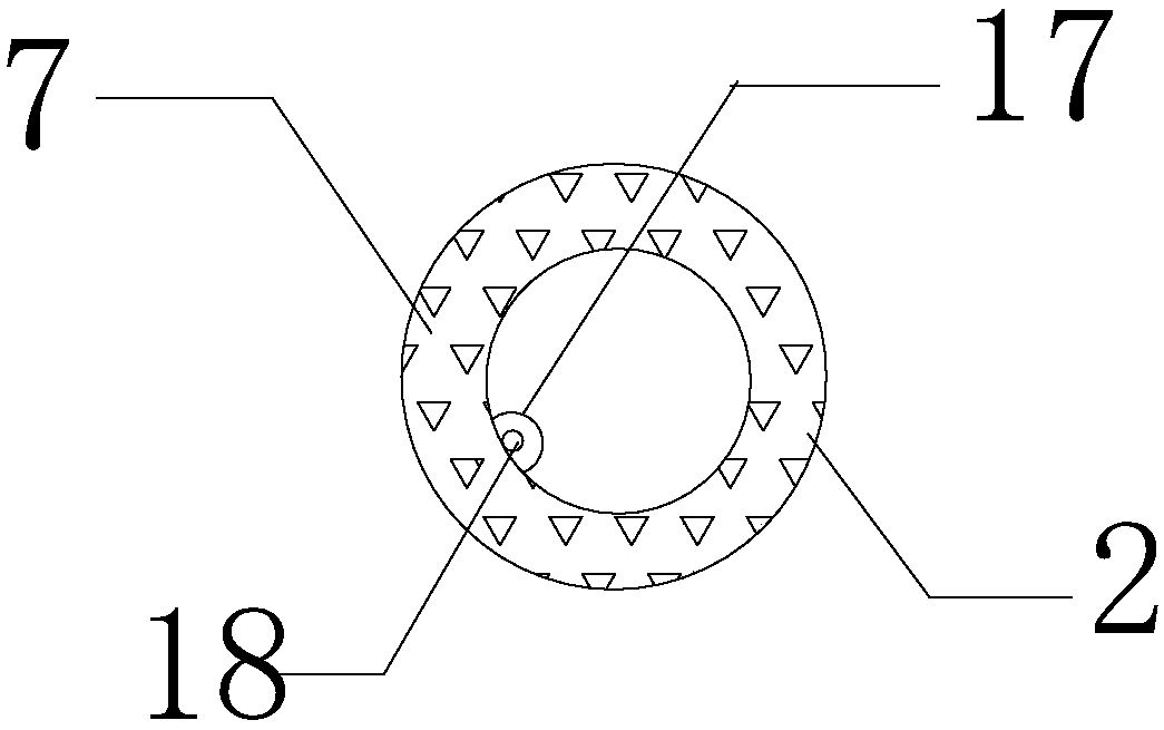
[0028] like Figure 1-6 It shows an embodiment of a portable household electric drill of the present invention, including a drill body 1 and a drill clip 2, the drill clip 2 is installed on the front end of the drill body 1, the drill body 1 includes a handle 3 and a placement cavity 4, and the placement cavity 4 A motor 5 is installed, and the output shaft of the motor 5 is connected with a bearing 6, and the other end of the bearing 6 is connected with a drill bit clamp 2, and a metal impact block and a metal gear are installed on the bearing 6, and a scratch-proof layer is provided on the inner wall of the drill bit clamp 2 7. The top of the handle 3 is a 匚...


PUM


Abstract

The invention discloses a portable household electric drill, which includes a drill body and a drill clip. The drill body includes a handle and a placement cavity. A motor is installed in the placement cavity. Blocks and metal gears, the inner wall of the drill clip is provided with a scratch-resistant layer, and the top of the handle is connected to a placement cavity through the shaft body, a frame-shaped frame is installed at the bottom of the outer side of the cavity, and a folding organ protective cover is installed in the frame-shaped frame. Both ends of the foldable organ protective cover are fixed with hard plates, a support positioning rod is installed under the storage cavity, a limit block is installed at the front end of the storage cavity, and a central control circuit board is installed in the storage cavity, and the central control circuit board is electrically connected to a The signal transmission device is connected with a speed regulating device, and the inner wall of the drill bit holder is provided with shrapnel. The invention has the characteristics that the drill bit can work at multiple angles, has strong flexibility, can optimize the surrounding environment at the same time, and can ensure the safety of workers when replacing the drill bit.

Description

technical field [0001] The invention relates to the field of electric tools, in particular to a portable household electric drill. Background technique [0002] Electric drill is a drilling tool powered by electricity. It is a conventional product in electric tools and is also the most demanded electric tool product. Electric drill products are suitable for drilling holes in steel, wood and plastic, and are the most used among hand-held electric tools. One of the most popular tools, the electric drill is the most commonly used electric tool. It has the advantages of convenience, low price, and portability, and is well received by workers in the hardware and decoration industries; [0003] Due to the ventilation and heat dissipation of the electric drill, there is a lot of dust inside after long-term use. The dust will mix and deteriorate the lubricating oil on the gears and bearings and dry up, which will aggravate wear and tear, especially if it is used in an alternative wa...

Claims


Application Information

Patent Timeline
Patent Type & Authority Applications(China)
IPC IPC(8): B23B45/02
CPCB23B45/02B23B45/003
Inventor 徐应盈
Owner 徐应盈
Learn More