

Radially-rotating heat pipe structure for cooling high-speed electric spindle inner cavity
A high-speed motorized spindle and internal chamber technology, used in metal processing machinery parts, maintenance and safety accessories, metal processing equipment, etc. It has the effect of small structural modification, compact structure and low cost
- Summary
- Abstract
- Description
- Claims
- Application Information
AI Technical Summary
Problems solved by technology
Method used
Image

Examples
Embodiment Construction
[0018] The present invention will be described in detail below in conjunction with the accompanying drawings and embodiments.
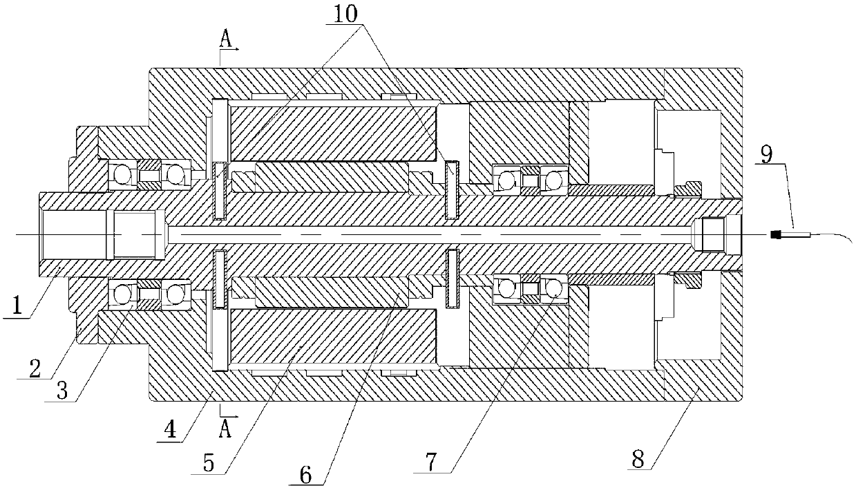
[0019] refer to figure 1 , a radially rotating heat pipe structure for cooling the internal chamber of a high-speed electric spindle, including a rotating shaft 1 with a central through hole processed inside, the front end of the rotating shaft 1 is supported on the front end of the electric spindle housing 4 through the front bearing group 3, and is installed on the The front end cover 2 on the outside of the front bearing assembly 3 realizes sealing and fixing; the middle part of the rotating shaft 1 and the motor rotor 6 are interference fit together, and the motor stator 5 matched with the motor rotor 6 is fixed on the electric spindle shell 4, and the motor stator 5 and the motor rotor 6 constitutes the main shaft motor; the rear end of the rotating shaft 1 is supported on the rear end of the electric spindle housing 4 through the rear bearing gr...
PUM
 Abstract
Description
Claims
Application Information