Steel pipe sand blasting rust removing device

A technology for sand blasting and rust removal and steel pipe, which is applied to used abrasive treatment devices, abrasive jet machine tools, abrasives, etc., can solve the problems of mirror pollution, bad mirror and safety problems, affecting the quality of steel pipe 100 rust removal, etc. , to reduce pollution and ensure the effect of rust removal

Pending Publication Date: 2018-02-23
江苏鑫德龙环保科技有限公司
View PDF0 Cites 2 Cited by
  • Summary
  • Abstract
  • Description
  • Claims
  • Application Information

AI Technical Summary

Problems solved by technology

[0003] But the mode of sandblasting directly at steel pipe 100 inner wall like this has following several shortcomings, the one, just start sandblasting when inserting certain depth in steel pipe 100 because sandblasting gun is chewed 102, and the shot sand flow that sandblasting gun is chewed 102 sprays is forward , which causes a part of the end position of the steel pipe 100 to be treated by sand blasting at all, thereby affecting the derusting quality of the steel pipe 100; the second is that the end of the steel pipe 100 inserted into the sandblasting gun nozzle 102 is open, and the shot sand 200 sometimes It will rebound from the end of the steel pipe 100, thereby causing a bad ring mirror and safety problems in the workplace; the third is that when sandblasting, since both ends of the steel pipe are open, the dust overflow caused by sandblasting will cause the pollution of the ring mirror

Method used


Image

  • Steel pipe sand blasting rust removing device
  • Steel pipe sand blasting rust removing device
  • Steel pipe sand blasting rust removing device

Examples


Embodiment Construction

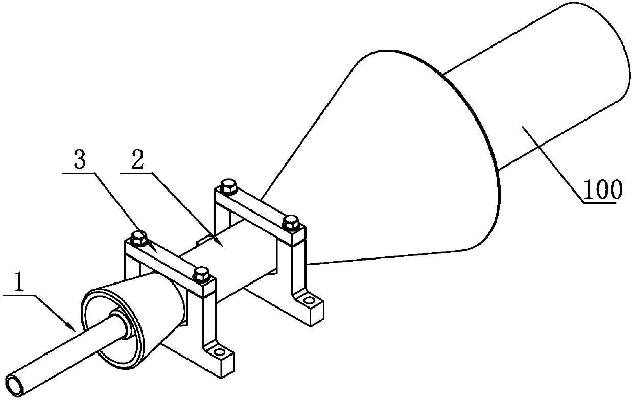
[0024] Such as Figure 2 to Figure 7 As shown, a steel pipe blasting and derusting device according to the present invention is used for blasting and derusting the inner wall of the steel pipe 100 . The steel pipe sandblasting derusting device includes a sandblasting gun 1 and a sandblasting positioning assembly.

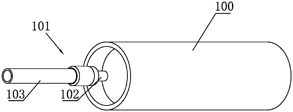
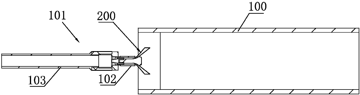
[0025] The sandblasting gun 1 has a sandblasting gun nozzle 11 for scattering sand shot 200 outward and a sandblasting pipe 12 for delivering sand shot 200 to the sandblasting gun nozzle 11 . The sandblasting pipe 12 is connected with the sandblasting gun nozzle 11 . The sandblasting gun nozzle 11 can spray the shot sand 200 outwards at a certain speed in the form of scattering.

[0026] The blasting positioning assembly includes a positioning tube 2 and a fixing seat 3 for installing and fixing the positioning tube 2 . The two ends of the positioning pipe 2 are respectively a first end 21 for covering the sandblasting gun nozzle 11 and a second end 22 for coveri...


PUM


Abstract

The invention relates to a steel pipe sand blasting rust removing device. The steel pipe sand blasting rust removing device comprises a sand blasting gun and a sand blasting positioning assembly. Thesand blasting positioning assembly comprises a positioning pipe and a fixing base. The two ends of the positioning pipe are a first end portion used for covering a sand blasting gun nozzle and a second end portion used for covering the end portion of a steel pipe. The sand blasting gun nozzle of the sand blasting gun stretches into the positioning pipe from the first end portion, the second end portion is in a horn mouth shape, and the pipe diameter of the second end portion is gradually increased in the outward extending direction of the positioning pipe. Pellet sand flow sprayed out throughthe sand blasting gun nozzle impacts on the steel pipe in the positioning pipe so that an oxidization layer on the inner wall of the steel pipe can be removed, accordingly, dust generated through sandblasting can be closed in the positioning pipe, it is guaranteed that dust does not overflow, and pollution to the environment due to sand blasting is greatly reduced. Due to the fact that the sand blasting gun nozzle starts to conduct sand blasting treatment on the steel pipe in the positioning pipe, the end portion of the steel pipe can be cleaned thoroughly through sand blasting, and the rustremoving effect of the steel pipe is guaranteed.

Description

technical field [0001] The invention belongs to the field of steel pipe derusting treatment, and in particular relates to a steel pipe sand blasting derusting device. Background technique [0002] At present, for the sandblasting and rust removal of the inner surface of the steel pipe with a diameter of ¢50-¢250, most of them are manually (or mechanically) inserted into the steel pipe 100 from one end of the steel pipe 100 to start sandblasting. The sand gun nozzle 102 and the sand blast pipe 103 that deliver the sand shot 200 to the sand blast gun nozzle 102. The inner wall of the steel pipe 100 removes the oxide layer under the impact of the high-speed shot sand flow, so as to achieve a certain surface quality, such as figure 1 with figure 2 shown. [0003] But the mode of sandblasting directly at steel pipe 100 inner wall like this has following several shortcomings, the one, just start sandblasting when inserting certain depth in steel pipe 100 because sandblasting g...

Claims


Application Information

Patent Timeline
IPC IPC(8): B24C1/08B24C3/32B24C9/00
CPCB24C1/086B24C3/325B24C9/00B24C9/003
Inventor 赵勇茅正龙施小军殷成伟
Owner 江苏鑫德龙环保科技有限公司
Why Eureka
Try Eureka