
Bicycle with power-enhanced accelerating device

A technology for acceleration devices and bicycles, applied in non-mechanical gear transmissions, vehicle components, vehicle gearboxes, etc., can solve the problems of plastic pipes that are prone to explosion, labor and fatigue, etc., and achieve simple structure, reasonable design, and good shock absorption effect of effect

Pending Publication Date: 2018-02-23
肖宜
View PDF0 Cites 0 Cited by
  • Summary
  • Abstract
  • Description
  • Claims
  • Application Information

AI Technical Summary

Problems solved by technology

[0002] As an environmentally friendly means of transportation, bicycles are used by more and more people for transportation, or as fitness equipment for riding and exercising, or for short- and medium-distance travel. In terms of acceleration, it is also reflected that it is very laborious and prone to fatigue when riding uphill and long distances, and the existing bicycle technology converts the periodically changing force of human gravity on the seat cushion and the force of very uneven road bumps into power. There are very few of them, and few of them convert the periodically changing force on the seat cushion into power through the spring and cylinder hydraulic oil circuit, but because the stiffness coefficient of each spring is fixed, it cannot cope well with different body types. The heavy cyclist can't cope well with the force applied to the pedals when the cyclist rides fast and slow, and the amount of hydraulic oil pressed out of the oil cylinder is not the same as that of the hydraulic pressure. The displacement of the motor does not match the problem, and when the air pressure in the cylinder part is insufficient, it will lead to a high pressure, the highest time is more than ten megabytes, so the plastic pipe is easy to burst. In view of the above situation, a booster can be designed. Accelerator bicycle to solve the above problems

Method used


Image

  • Bicycle with power-enhanced accelerating device
  • Bicycle with power-enhanced accelerating device
  • Bicycle with power-enhanced accelerating device

Examples


Embodiment Construction

[0016] The present invention will be further described below in conjunction with accompanying drawing:

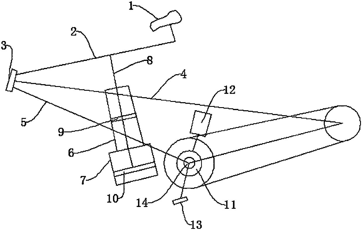
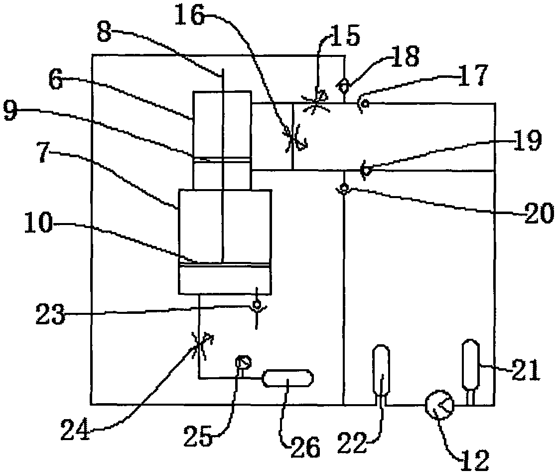
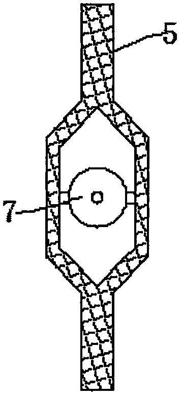
[0017] Such as Figure 1-Figure 4 As shown, a bicycle equipped with a power-increasing acceleration device includes a seat cushion 1, which is fixed on the upper frame tube 2, and the upper frame tube 2 and the front frame tube 3 are connected by positioning and swinging. The frame pipe 3 is also rigidly connected with the middle frame pipe 4 and the lower frame pipe 5. The upper frame pipe 2, the front frame pipe 3, the middle frame pipe 4 and the lower frame pipe 5 are all made of metal materials. The traditional plastic pipe has greater strength, can avoid pipe explosion, and has high safety. The upper frame pipe 2 is also connected with the piston rod 8 for positioning and swinging. The piston rod 8 is also equipped with piston A9 and piston B10. B10 is used to compress the air in the lower cavity of the cylinder 7, the piston A9 is located in the cylinder 6, the pisto...


PUM


Abstract

The invention discloses a bicycle equipped with a power-increasing acceleration device, which includes a seat cushion, the seat cushion is fixed on an upper frame tube, and the upper frame tube and the front frame tube are connected by positioning and swinging. The front frame tube is also rigidly connected with the middle frame tube and the lower frame tube, and the upper frame tube is also connected with the piston rod for positioning and swinging. The piston rod is also equipped with piston A and piston B. Piston A is located in the cylinder. The beneficial effect is that the bicycle equipped with a booster acceleration device according to the present invention has a simple structure and a reasonable design, and the volume of the air storage tank can be adjusted by changing the volume to change the main structure of the cylinder and the piston. The stiffness coefficient of the formed gas spring can deal with the amount of hydraulic oil that the oil cylinder presses out due to the large difference in force applied to the pedal when the rider is riding a bicycle at a fast speed and at a slow speed. Problems that do not match the hydraulic motor displacement.

Description

technical field [0001] The invention relates to the field of bicycles, in particular to a bicycle equipped with a booster acceleration device. Background technique [0002] As an environmentally friendly means of transportation, bicycles are used by more and more people for transportation, or as fitness equipment for riding and exercising, or for short- and medium-distance travel. In terms of acceleration, it is also reflected that it is very laborious and prone to fatigue when riding uphill and long distances, and the existing bicycle technology converts the periodically changing force of human gravity on the seat cushion and the force of very uneven road bumps into power. There are very few of them, and few of them convert the periodically changing force on the seat cushion into power through the spring and cylinder hydraulic oil circuit, but because the stiffness coefficient of each spring is fixed, it cannot cope well with different body types. The heavy cyclist can't c...

Claims


Application Information

Patent Timeline
IPC IPC(8): B62M19/00
CPCB62M19/00
Inventor 肖宜
Owner 肖宜
Learn More