Spinning cake clamp

A silk cake and jig technology, which is applied in the field of silk cake jigs, can solve the problems of increased jig manufacturing costs, inability to move jigs synchronously, and low clamping efficiency, so as to reduce the number of parts, improve clamping efficiency, and reduce manufacturing costs. Effect

Pending Publication Date: 2018-02-23
HANGZHOU RUIGUAN TECH
View PDF8 Cites 4 Cited by
  • Summary
  • Abstract
  • Description
  • Claims
  • Application Information

AI Technical Summary

Problems solved by technology

[0004] However, the multiple clamps on the existing yarn cake clamp cannot move synchronously, and need to be driven by corresponding dr

Method used


Image

  • Spinning cake clamp
  • Spinning cake clamp
  • Spinning cake clamp

Examples


Embodiment Construction

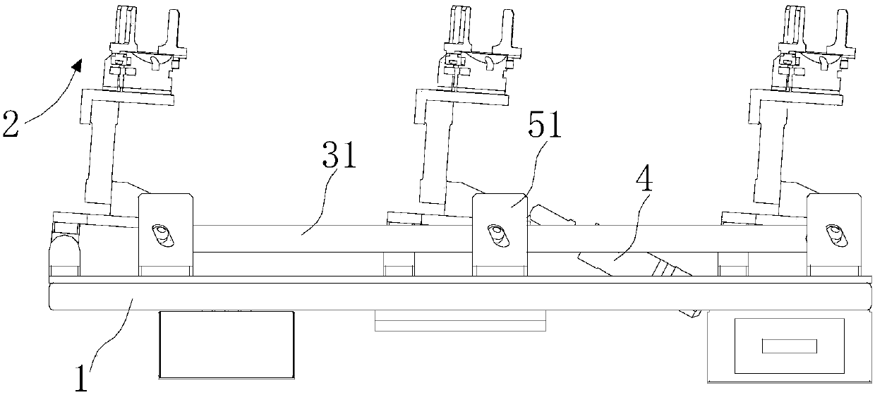
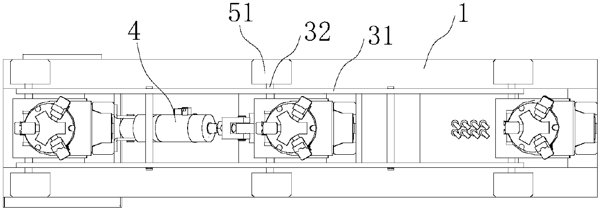
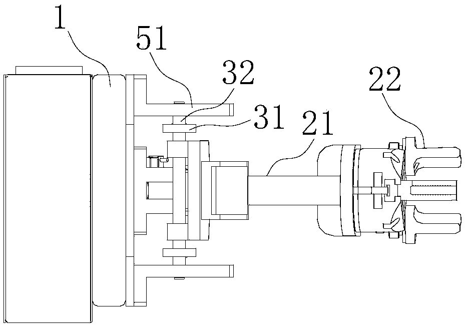
[0032] Such as Figure 1 ~ Figure 4 As shown, the present invention includes:

[0033] The mounting plate 1 is provided with a plurality of mounting positions 11 arranged along the same direction on the mounting plate 1,

[0034] A plurality of jaws 2, the plurality of jaws 2 are respectively hingedly arranged on the installation position 11,

[0035] The linkage mechanism 3 is used to link and connect multiple jaws 2,

[0036] The driving mechanism 4 is used to drive the driving mechanism 4 linked by multiple jaws 2;

[0037] Wherein linkage mechanism 3 comprises:

[0038] The linkage rod 31 is arranged along the direction of the installation position 11,

[0039] A plurality of driving rods 32 , the plurality of driving rods 32 are respectively fixedly threaded on the jaw 2 , and the ends of the driving rods 32 corresponding to the position of the linkage rod 31 are fixedly threaded on the linkage rod 31 .

[0040] In the present invention, the silk cake fixture coopera...


PUM


Abstract

The invention discloses a spinning cake clamp. The spinning cake clamp comprises an installing plate, a plurality of clamping jaws, a linkage mechanism and a driving mechanism; the installing plate isprovided with a plurality of installing positions arranged in the same direction, the multiple clamping jaws are hinged to the installing positions, the linkage mechanism is used for achieving linkedconnection of the multiple clamping jaws, and the driving mechanism is used for driving linkage of the multiple clamping jaws; the linkage mechanism comprises linkage rods arranged in the direction of the installing position and a plurality of driving rods correspondingly and fixedly penetrating the clamping jaws; and the ends, corresponding to the linkage rods, of the driving rods fixedly penetrate the linkage rods. The multiple clamping jaws on the spinning cake clamp achieves synchronized linkage matching, the multiple clamping jaws clamp different spinning cakes at the same time, and thespinning cake clamping efficiency is greatly improved; and in addition, only one driving mechanism for driving the clamping jaws to move needs to be arranged to achieve driving on the multiple clamping jaws, the number of components is greatly reduced, and the manufacturing cost is reduced.

Description

technical field [0001] The invention belongs to the technical field of chemical fiber processing and production, and in particular relates to a silk cake clamp. Background technique [0002] In the industrial production process, the cotton spinning yarn needs to be wound by a winding machine to form a silk cake, and then the silk cake is transported to the material rack for hanging storage. The material rack means that the front and back sides of the rack body can hang materials, and both sides of the rack body are provided with a number of stakes, and the stakes can be pierced with silk cakes to be processed or transported. During the processing and transportation of the silk cake, the feeding and unloading operations of the silk cake are all done by machinery, and the feeding or unloading robot is located on one side of the material rack for operation. When the operation on one side is completed, the material rack needs to be removed. Operate on the other side of the mach...

Claims


Application Information

Patent Timeline
IPC IPC(8): B65G47/90
CPCB65G47/902B65G47/907
Inventor 张家春
Owner HANGZHOU RUIGUAN TECH
Why Eureka
Try Eureka