Use method of lifting machine

A technology of lifts and lifting columns, which is applied in the field of lifts, can solve the problems of reducing the service life of the lift, the large impact force of the lifting part and the supporting part, and the damage of the lifting part, so as to reduce the degree of damage, improve the stability of work, and avoid being damaged. damage effect

Inactive Publication Date: 2018-02-23
张玲琳
View PDF0 Cites 2 Cited by
  • Summary
  • Abstract
  • Description
  • Claims
  • Application Information

AI Technical Summary

Problems solved by technology

[0003] However, in small and medium-sized load-carrying screw elevators, when the motor fails or the power is cut off, the lifting part of the elevator will suddenly fall, which will cause a large impact force between the lifting part and the supporting part, which is easy to cause lifting. Partially damaged internally, which reduces the service life of the lift

Method used


Image

  • Use method of lifting machine
  • Use method of lifting machine

Examples


Embodiment

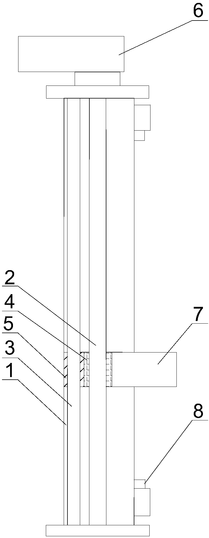
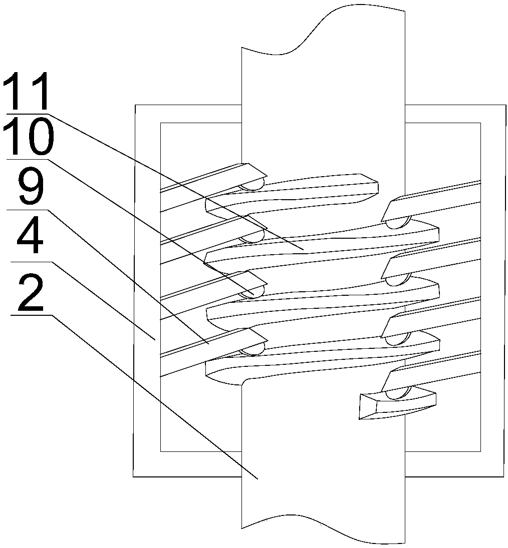
[0022] Such as figure 1 and figure 2 As shown, a method for using a lift in the present invention includes the following steps. The screw mandrel 2 is rotated and installed in the lifting column 1. Driven by the driving mechanism, the screw mandrel 2 rotates to drive the rotating cylinder 4 on the screw mandrel 2 to rise or is to descend, and the chuck 7 connected to one end of the rotating cylinder 4 clamps the workpiece up or down; when rising, the thread 11 on the screw rod 2 is connected with the support block 9 on the inner wall of the rotating cylinder 4, and is located in the groove The roller 10 is in line contact with the upper surface of the thread 11. Since the support block 9 is distributed on the inner wall of the rotating cylinder 4 along the direction of rotation of the thread 11 on the screw 2, when the screw 2 rotates, the roller 10 moves upward along the upper surface of the thread 11. , to realize the upward movement of the entire rotating cylinder 4; wher...


PUM


Abstract

The invention discloses a method for using a lift. The guide sleeve can adjust the force balance at both ends of the rotating cylinder, so as to avoid excessive force on one end of the chuck and cause breakage at the joint between the chuck and the rotating cylinder. When the motor fails, The rollers can buffer the instantaneous impact force between the support block and the thread, reduce the damage of the rotating cylinder and improve the stability of the elevator.

Description

technical field [0001] The invention relates to a lift, in particular to a method for using the lift. Background technique [0002] The traditional screw jack is generally composed of worm gear, box, bearing, screw and other parts; the working principle is: the motor or manual drive the worm to rotate, the worm drives the worm gear to decelerate the rotation, the inner cavity of the worm gear is processed into an internal thread, and drives the screw up and down Moving, due to the worm gear and worm inside, the deceleration effect of the lead screw achieves the effect of amplifying the thrust. As a modern lifting equipment, the screw elevator has a wide range of applications, and the development of the screw elevator is also very rapid. It is not difficult to draw the development direction of the elevator in the future, among which speed, variable speed and safety performance are the key points, and the importance of safety It is very important in all kinds of equipment. Th...

Claims


Application Information

Patent Timeline
Patent Type & Authority Applications(China)
IPC IPC(8): B66F7/14B66F7/28B66F17/00
CPCB66F7/14B66F7/28B66F17/00
Inventor 张玲琳
Owner 张玲琳
Why Eureka
Try Eureka