A mechanical arm device with automatic locking and mutual unlocking
An automatic locking and mechanical arm technology, applied in the direction of lifting devices, etc., can solve the problems of the safety and operability of the climbing frame, the increase of labor intensity of workers, and the impact on the construction process, so as to avoid safety and reliability problems, Reduce the labor intensity of workers and realize the effect of fully automated operation
- Summary
- Abstract
- Description
- Claims
- Application Information
AI Technical Summary
Problems solved by technology
Method used
Image
Examples
Embodiment 1
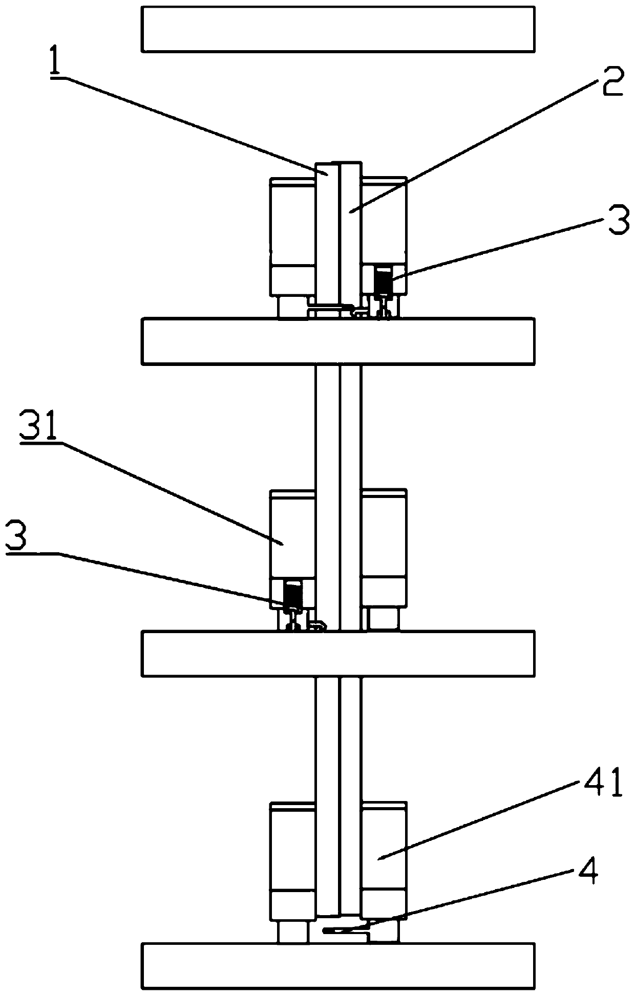
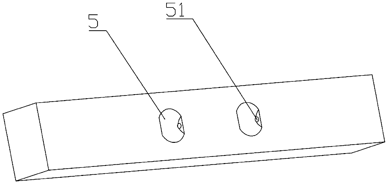
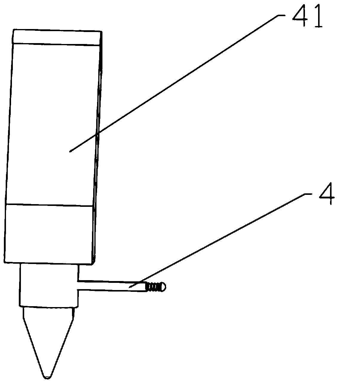
[0054] Such as figure 1 and figure 2 As shown, the automatic locking and mutual unlocking mechanical arm device provided by Embodiment 1 of the present invention is used in a climbing device. The climbing device includes a left guide rail 1 and a right guide rail 2 arranged adjacently. 1 and the first robot arm 31 on the right guide rail 2, the locking mechanism 3 installed on the first robot arm 31, the unlocking mechanism arranged on the left guide rail 1 and the right guide rail 2, and the positioning structure 5 arranged on the building. Both the first mechanical arm 31 and the unlocking structure 4 located on the left guide rail 1 and the right guide rail 2 can rotate freely downward but can only rotate upward to a certain angle. Such as Figure 3A As shown, the unlocking mechanism in this embodiment includes a second mechanical arm 41 and an unlocking member 4 installed on the second mechanical arm 41 . Such as Figure 3B As shown, in other embodiments, the unlockin...
Embodiment 2
[0060] Compared with the first embodiment, the second embodiment differs in that it also includes a fourth mechanical arm 9 with both locking and unlocking functions, that is, the fourth mechanical arm 9 is provided with a locking mechanism 3 and an unlocking member 4 at the same time.
[0061] Such as Figure 9A and Figure 9B As shown, the third mechanical arm 6 and the fourth mechanical arm 9 are sequentially installed on the left guide rail 1 from top to bottom, and the first mechanical arm 31 and the second mechanical arm 41 are sequentially installed on the right guide rail 2 from top to bottom. , the first mechanical arm 31 and the second mechanical arm 41 are respectively installed with a locking mechanism 3 and an unlocking member 4 . The positions of the fourth mechanical arm 9 on the left guide rail 1 and the right guide rail 2 , the locking mechanism 3 and the unlocking member 4 on the first mechanical arm 31 and the second mechanical arm 41 correspond to each oth...
Embodiment 3
[0064] Compared with the first embodiment, the third embodiment differs in that the first mechanical arm 31 and the locking mechanism 3 in the third embodiment are different. Such as Figure 10 shown, also refer to Figure 11 and Figure 12 , the locking mechanism 3 in this embodiment includes a guide slider 321 , a pressing slider 322 , a pendulum 330 , a first compression spring 324 and a first torsion spring 331 . The first mechanical arm 31 is provided with a first chamber 34 and a second chamber 35 which communicate with each other, wherein, the left side wall or the right side wall of the first chamber 34 is provided with a transverse, communicating with the first chamber 34 and the second guide hole 37 of the outside world, a part of the second chamber 35 is located on the locking block 33, and the left side wall or the right side wall of the second chamber 35 on the locking block 33 is provided with a transverse, communicating with the second guide hole 37. Two cham...
PUM
 Abstract
Description
Claims
Application Information
 - R&D
- Intellectual Property
- Life Sciences
- Materials
- Tech Scout
- Unparalleled Data Quality
- Higher Quality Content
- 60% Fewer Hallucinations
Browse by: Latest US Patents, China's latest patents, Technical Efficacy Thesaurus, Application Domain, Technology Topic, Popular Technical Reports.
© 2025 PatSnap. All rights reserved.Legal|Privacy policy|Modern Slavery Act Transparency Statement|Sitemap|About US| Contact US: help@patsnap.com


