Non-slide fiber strip storage device with U-shaped bottom part

A storage device, technology for fiber strips in the fields of fiber handling, fiber feeding, textiles and papermaking

Active Publication Date: 2018-02-23
JINGWEI TEXTILE MASCH CO LTD
View PDF7 Cites 9 Cited by
  • Summary
  • Abstract
  • Description
  • Claims
  • Application Information

AI Technical Summary

Problems solved by technology

However, in the prior art, there is no device that can successfully turn over and store the fiber sliver

Method used


Image

  • Non-slide fiber strip storage device with U-shaped bottom part
  • Non-slide fiber strip storage device with U-shaped bottom part
  • Non-slide fiber strip storage device with U-shaped bottom part

Examples


Embodiment Construction

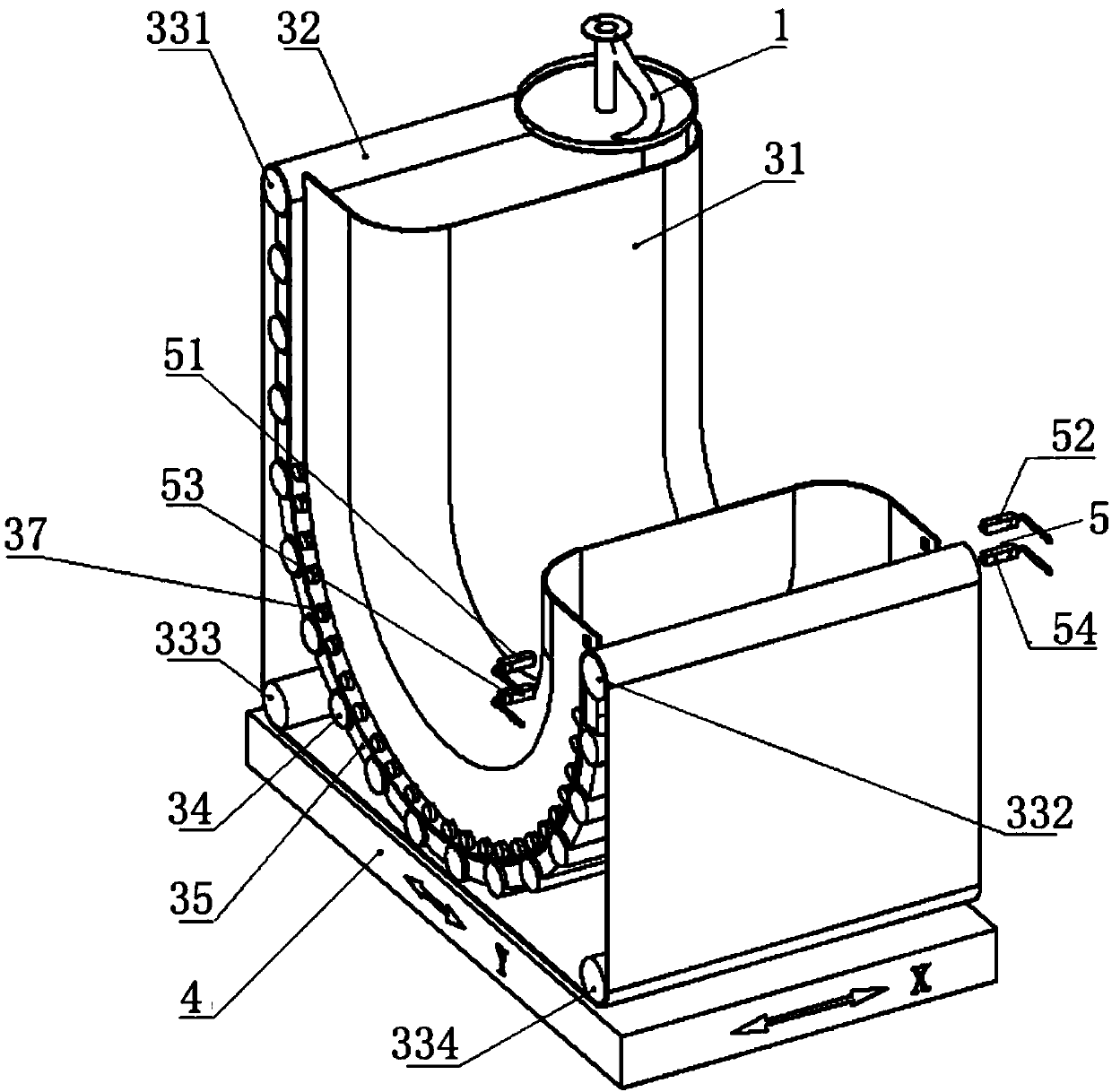
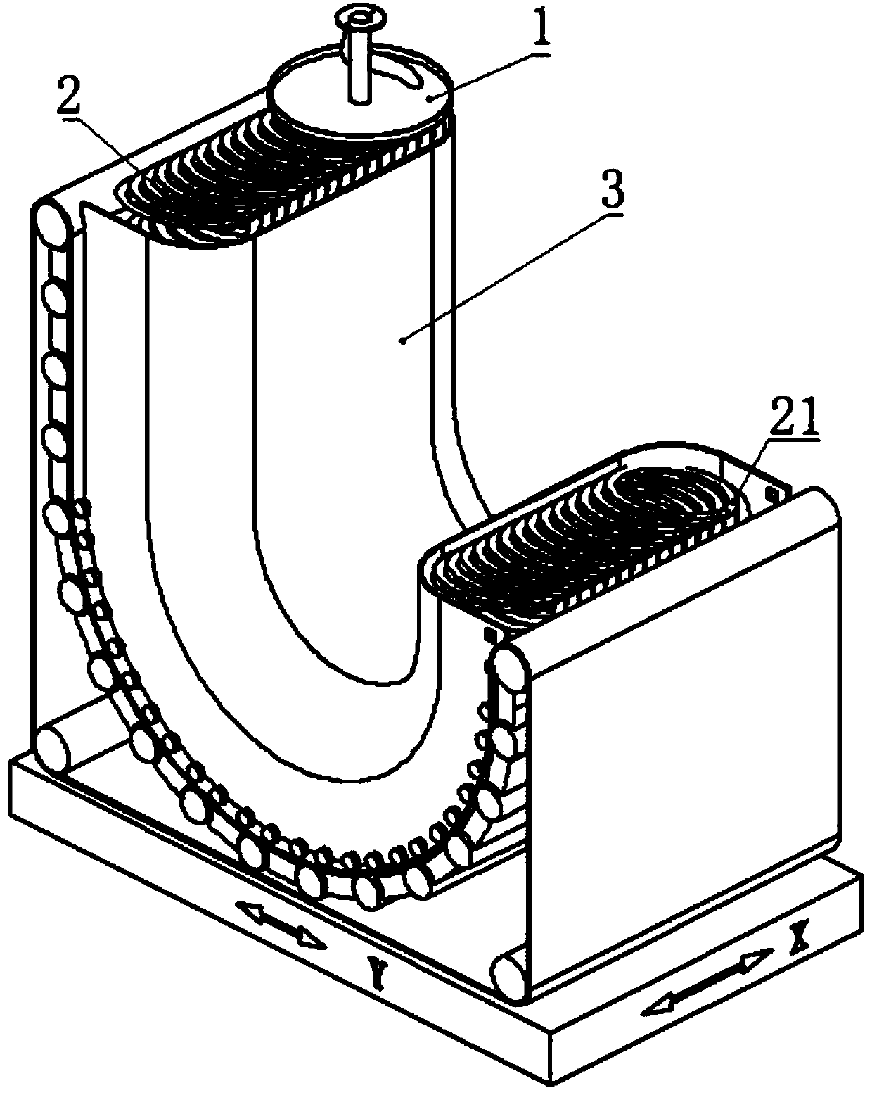
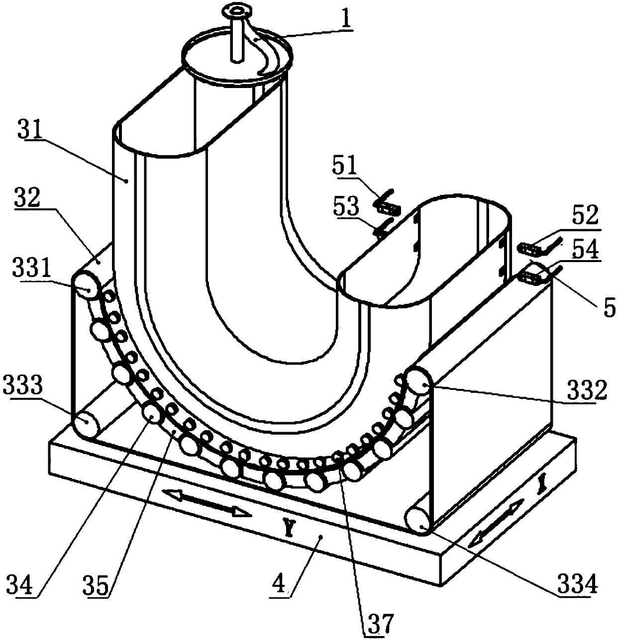
[0022] In Publication No. 1609291 "Method and Device for Dynamic Storage of Cotton Sliver", the disclosed technical solution is: "The cotton sliver output by the carding machine or the combing machine is stacked in a circular or oblong shape by the coiled sliver assembly. In the longitudinal section of the sliver reversing and dynamic reservoir adapted to the profile of the laminated sliver, the longitudinal section of the sliver reversing and dynamic reservoir is a "U"-shaped channel in which the sliver is placed After 180-degree inversion, it is dynamically stored in the sliver inversion and dynamic storage, and the head end of the ring-shaped laminated sliver can be drawn out of the sliver dynamic storage without interruption."

[0023] One of the matching forms is: "the self-rotating sliver (the upper part of the ordinary coiler) and the sliver inverting and dynamic storage with a long circular cross-section and a "U"-shaped pipe in the longitudinal section, the sliver inve...


PUM


Abstract

The invention provides a non-slide fiber strip storage device with U-shaped bottom part. The non-slide fiber strip storage device comprises a fiber strip storage device, a mounting base, storage quantity sensors, a transmission device and a support device, wherein the longitudinal cross section of the fiber strip storage device is in an U shape; the transmission device is arranged on the mountingbase; the storage quantity sensors are arranged at the tail end of the fiber strip storage device; the transmission device is provided with a conveying belt and main support rolls of the conveying belt; the main support rolls of the conveying belt are arranged at both ends of the support device, the shape of the support device is matched with the shape of the bottom surface of the fiber strip storage device, and the support device passes through the lowest point of the bottom surface of the fiber strip storage device; the part, passing through the support device, of the conveying belt forms amovable bottom surface for the fiber strip storage device; a rotary strip circling device is arranged above an inlet of the fiber strip storage device, and is rotationally arranged on a fixed machineframe.

Description

technical field [0001] The invention relates to a U-shaped bottom non-sliding fiber strip storage device used in cotton spinning engineering to realize automatic connection between a plurality of carding machines and a drawing frame for continuous production. Background technique [0002] In existing cotton and cotton type chemical fiber spinning engineering, the cotton slivers produced by carding machine are placed in continuous and orderly circles, in bottomed, cylindrical (or rectangular) sliver cans. After a card can is filled with fiber sliver, the card changes to another can to continue production. The sliver cans filled with fiber sliver produced by several cards are transported to the sliver storage area. When the draw frame is in production, the raw sliver cans filled with fiber slivers produced by different carding machines are transported to the draw frame. Then it is processed by drawing frame. This production process has the following characteristics: 1. The ...

Claims


Application Information

Patent Timeline
Patent Type & Authority Applications(China)
IPC IPC(8): D01G23/00
CPCD01G23/00
Inventor 杨华明王跃李界宏陈朝龙倪远铃木雅博金宏健崔凤贤赵云波
Owner JINGWEI TEXTILE MASCH CO LTD
Why Eureka
Try Eureka