Induction cooker cooking utensil and dry heating prevention control method thereof
A control method and the technology of an induction cooker, which are applied in household appliances, household stoves/stoves, electric heating fuels, etc., can solve the problems of dry burning of pots, damage of pots, dry burning, etc. Effect
- Summary
- Abstract
- Description
- Claims
- Application Information
AI Technical Summary
Problems solved by technology
Method used
Image
Examples
Embodiment 1
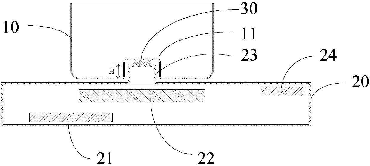
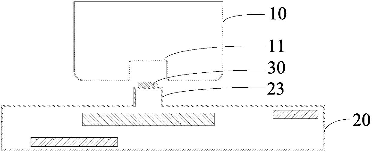
[0045] figure 2 It is a schematic structural diagram of the induction cooker provided in Embodiment 1 of the present invention; image 3 It is a schematic diagram of the split structure of the induction cooker provided in the first embodiment of the present invention, Figure 4 It is a schematic structural diagram of the inner liquid level in the cooker of the induction cooker provided in the first embodiment of the present invention is lower than the induction device; Figure 5 It is a structural schematic diagram showing that the liquid level in the cooker of the induction cooker is higher than that of the induction device provided in the first embodiment of the present invention, as shown in Fig. Figure 2-5 As shown, in this embodiment, the induction cooker includes: an induction cooker 20 and a pot 10. The induction cooker 20 is provided with a coil disc 22, a control board 24 and a power supply board 21. The coil disc 22 is electrically connected to the control board 2...
Embodiment 2
[0058] Image 6 It is a schematic diagram of the split structure of the induction cooker provided in the second embodiment of the present invention, such as Image 6 As shown, the difference between this embodiment and the above-mentioned embodiment is: in this embodiment, the induction device 30 is arranged on the concave surface of the inner recess 11, that is, the induction device 30 is arranged on the cookware 10 and is located in the inner recess 11 toward the convex portion 23, wherein the induction end of the induction device 30 is in contact with the concave surface of the inner recess 11, so that the induction end of the induction device 30 can sense the liquid level in the cooker 10. Therefore, when the induction device 30 is arranged on the concave portion 11 of the cookware 10, the other end of the induction device 30 can abut against the convex portion 23 when the cookware 10 is placed on the induction cooker 20, which is convenient for the induction device 30 It...
Embodiment 3
[0061] Figure 7 It is a schematic diagram of the split structure of the induction cooker provided in the third embodiment of the present invention, such as Figure 7 As shown, the difference between this embodiment and the above-mentioned embodiment is: in this embodiment, the convex portion 23 includes a side surface and a top portion, the inner concave portion 11 includes a side surface and a top portion, and the sensing device 30 is provided in the inner concave portion 11 and the convex portion. 23, specifically, the sensing device 30 may be provided on the side of the convex portion 23, or the sensing device 30 may also be provided on the concave side of the inner recess 11, wherein, when the sensing device 30 side is provided in the inner recess 11 on the concave side, even when there is residual liquid at the top of the inner recess 11, since the sensing device 30 is provided on the concave side of the inner recess 11, the sensing end of the sensing device 30 is in con...
PUM
 Abstract
Description
Claims
Application Information
 - R&D Engineer
- R&D Manager
- IP Professional
- Industry Leading Data Capabilities
- Powerful AI technology
- Patent DNA Extraction
Browse by: Latest US Patents, China's latest patents, Technical Efficacy Thesaurus, Application Domain, Technology Topic, Popular Technical Reports.
© 2024 PatSnap. All rights reserved.Legal|Privacy policy|Modern Slavery Act Transparency Statement|Sitemap|About US| Contact US: help@patsnap.com


