Industrial automatic waterproof power supply

An industrial automation and power supply technology, applied in electrical components, substation/distribution device enclosures, substation/switch layout details, etc. Problems such as poor effect, to achieve the effect of novel design concept, convenient movement, and labor saving

Inactive Publication Date: 2018-02-23
江苏当升智能装备科技有限公司
View PDF0 Cites 11 Cited by
  • Summary
  • Abstract
  • Description
  • Claims
  • Application Information

AI Technical Summary

Problems solved by technology

[0002] A power supply is a device that converts other forms of energy into electrical energy. With the development of science and technology and the improvement of people's living standards, power resources have become an indispensable resource in our lives. The requirements of the waterproof power supply are becoming more and more stringent, and the waterproof power supply is widely used. However, the use of the waterproof power supply is not automatic and humanized. Therefore, the demand for a waterproof power supply for industrial automation is increasing
[0003] Most of the waterproof power supplies currently on the market are fixed and cannot be changed automatically according to the needs of the specific environment, which is inconvenient to use and has a short service life; some waterproof power supplies do not have heat dissipation devices, which can easily cause Damage to the power supply, high cost of use; there are also some waterproof power supplies with poor waterproof effect, and there are certain dangers in the use process. Therefore, a waterproof power supply for industrial automation is proposed to solve the above problems.

Method used


Image

  • Industrial automatic waterproof power supply
  • Industrial automatic waterproof power supply
  • Industrial automatic waterproof power supply

Examples


Embodiment Construction

[0021] The following will clearly and completely describe the technical solutions in the embodiments of the present invention with reference to the accompanying drawings in the embodiments of the present invention. Obviously, the described embodiments are only some, not all, embodiments of the present invention. Based on the embodiments of the present invention, all other embodiments obtained by persons of ordinary skill in the art without making creative efforts belong to the protection scope of the present invention.

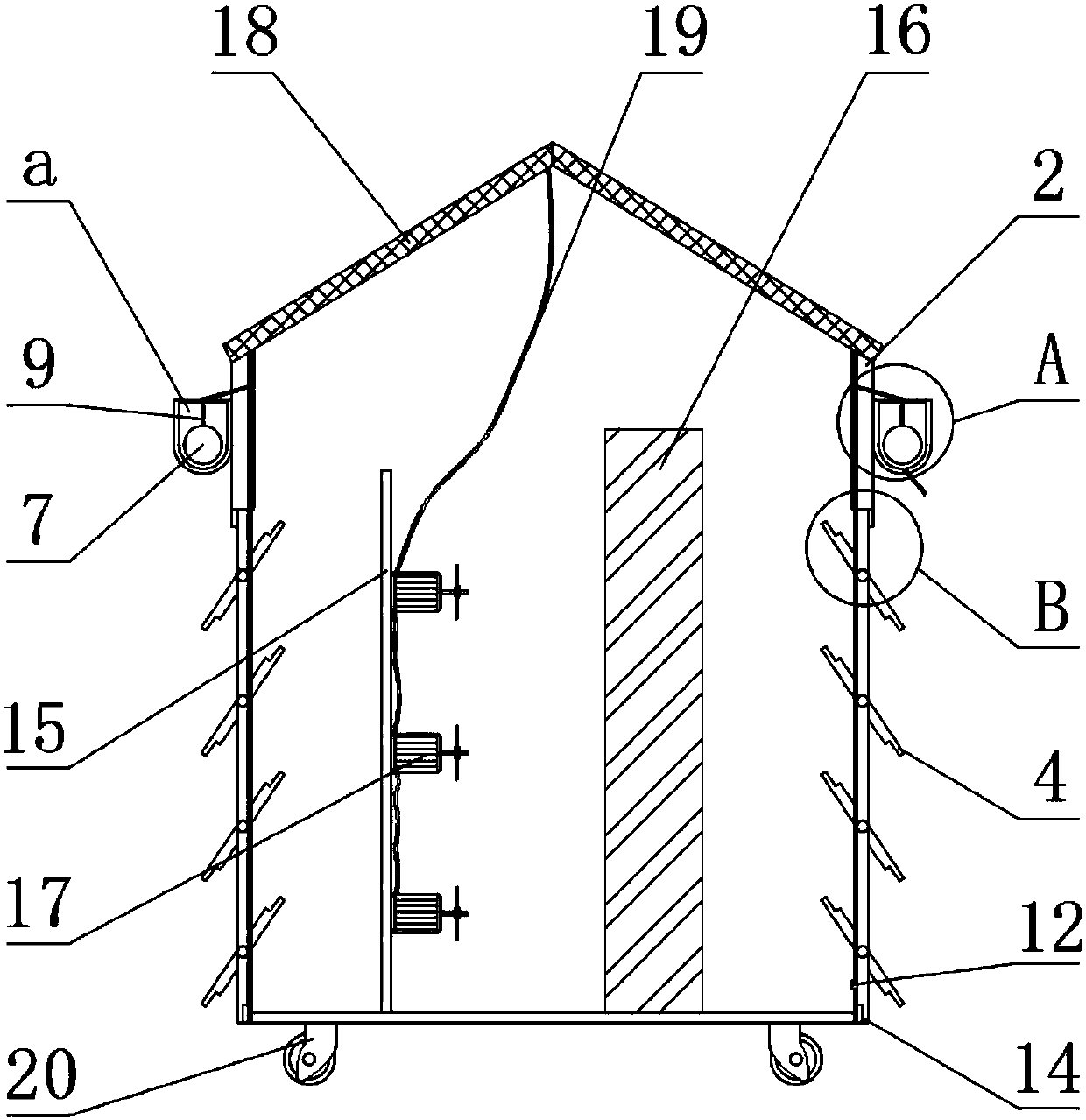
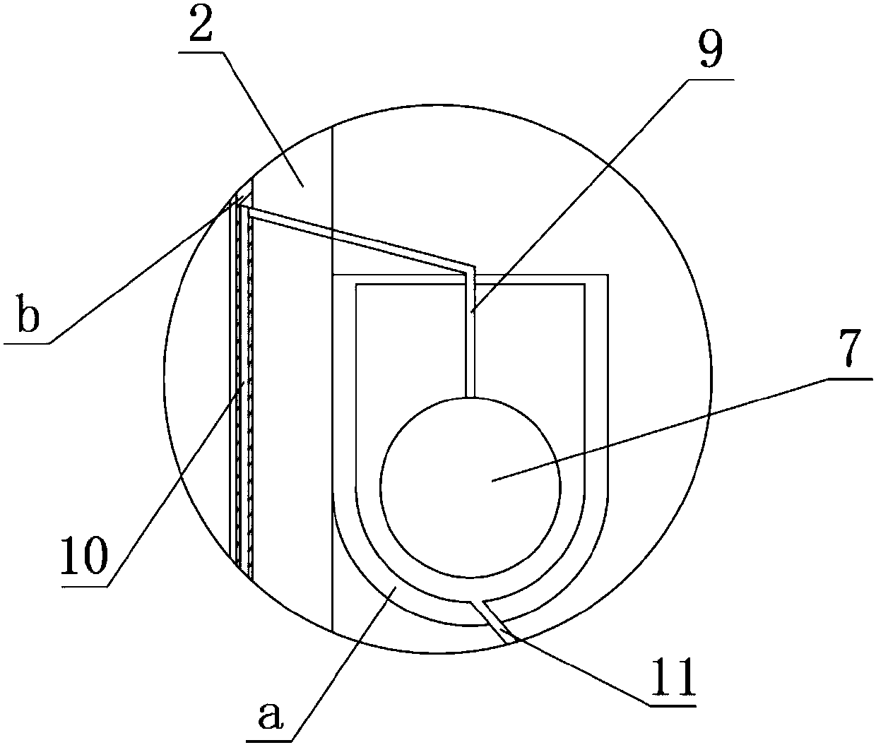
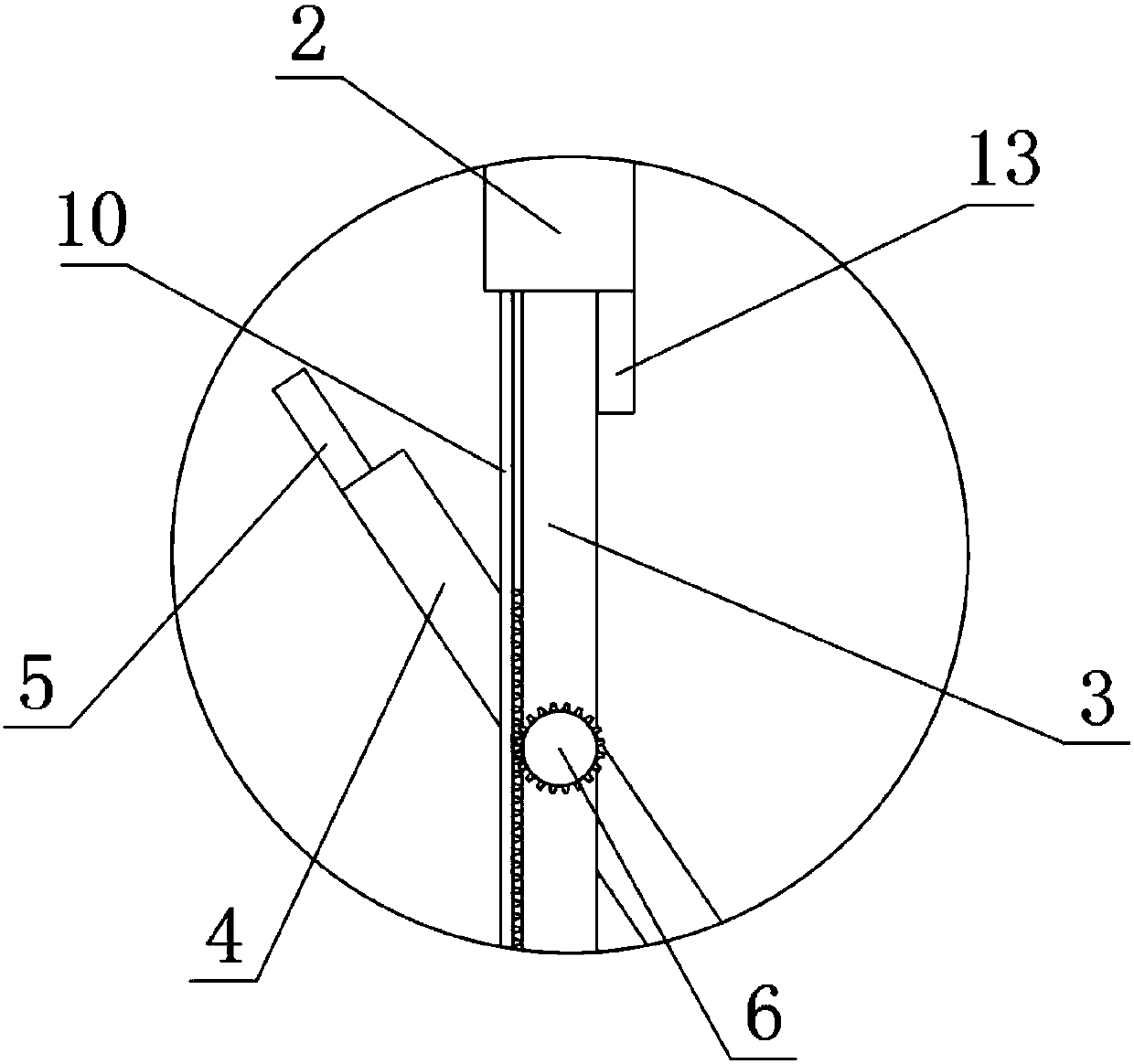
[0022] see Figure 1-4 , the present invention provides a technical solution:

[0023] A waterproof power supply for industrial automation, comprising a box body 1, the right side of the box body 1 is provided with a fixed plate 2, the bottom end of the fixed plate 2 is provided with a fixed rod 3, and the fixed rod 3 is rotated by a rotating shaft The louver blade 4 is connected, the two ends of the louver blade 4 are provided with a first baffle plate 5, th...


PUM


Abstract

The invention relates to the technical field of industrial power supplies, in particular to an industrial automatic waterproof power supply. The power supply comprises a box, a fixed plate is arrangedon the right side of the box, a fixed rod is arranged at the bottom end of the fixed plate, louvre blades are rotationally connected to the fixed rod through rotating shafts, first baffles are arranged at the two ends of each louvre blade, a gear is arranged at the front section of each rotating shaft, a water storage tank is arranged at the right side of the fixed plate, a floating ball is arranged in the water storage tank, limiting plates are arranged at the two sides of the floating ball, a connecting rod is fixedly connected to the top of the floating ball, and a rack is fixedly connected to the left upper end of the connecting rod. Accordingly, by means of the water storage tank, the floating ball, the gear, the rack and a drain pipe, when it rains, the louvre blades can be closed automatically, a power supply box is protected, and when the rain stops, the louvre blades are opened automatically to assist cooling; in this way, the idea is novel, design is scientific, the huge economic benefit and wide market prospect are achieved, and the power supply is worthy of application and popularization.

Description

technical field [0001] The invention relates to the technical field of industrial power supplies, in particular to a waterproof power supply for industrial automation. Background technique [0002] A power supply is a device that converts other forms of energy into electrical energy. With the development of science and technology and the improvement of people's living standards, power resources have become an indispensable resource in our lives. Waterproof power supplies are widely used, but the use of waterproof power supplies is not automatic and humanized enough. Therefore, the demand for a waterproof power supply for industrial automation is increasing. [0003] Most of the waterproof power supplies currently on the market are fixed and cannot be changed automatically according to the needs of the specific environment, which is inconvenient to use and has a short service life; some waterproof power supplies do not have heat dissipation devices, which can easily cause Da...

Claims


Application Information

Patent Timeline
Patent Type & Authority Applications(China)
IPC IPC(8): H02B1/46H02B1/56H02B1/28
CPCH02B1/28H02B1/46H02B1/565
Inventor 王君
Owner 江苏当升智能装备科技有限公司
Why Eureka
Try Eureka