

Garment production line with lighting brackets
A production line and clothing technology, applied in the direction of sewing tools, etc., can solve the problems of safety hazards in the production process, affect the quality of work, eye fatigue and other problems, achieve the effect of simplifying field wiring, good promotion value, and improving safety
- Summary
- Abstract
- Description
- Claims
- Application Information
AI Technical Summary
Problems solved by technology
Method used
Image

Examples
Embodiment 1
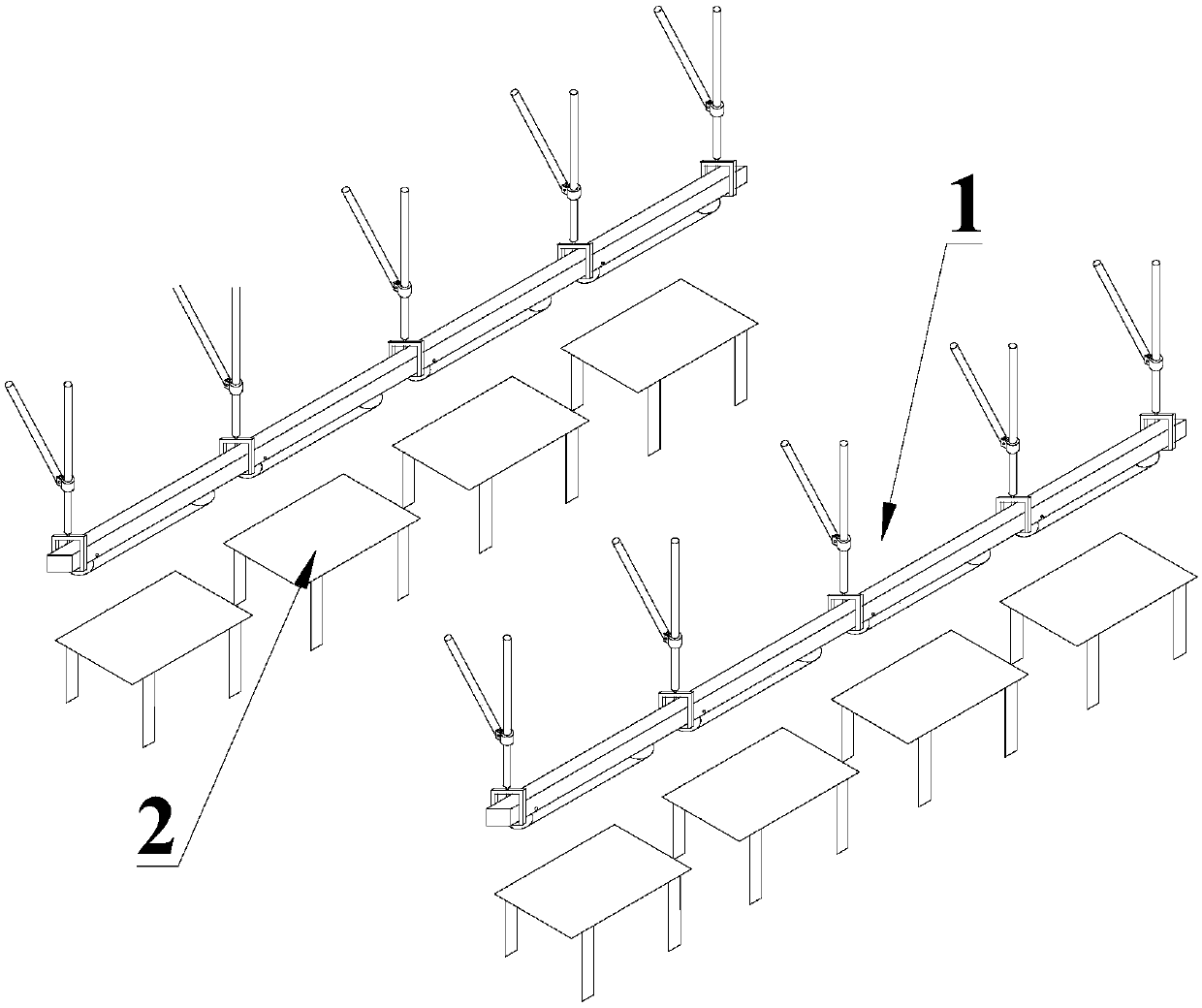
[0032] A garment production line, including an unwinding station, a cutting station, a sewing station, a buttonhole punching station, and an ironing station 21. The lighting device is arranged above each working station, and the ironing station is placed below. 21 as an example.
[0033] Such as figure 1 As shown, this embodiment includes a lighting device 1 and an ironing device 2 .
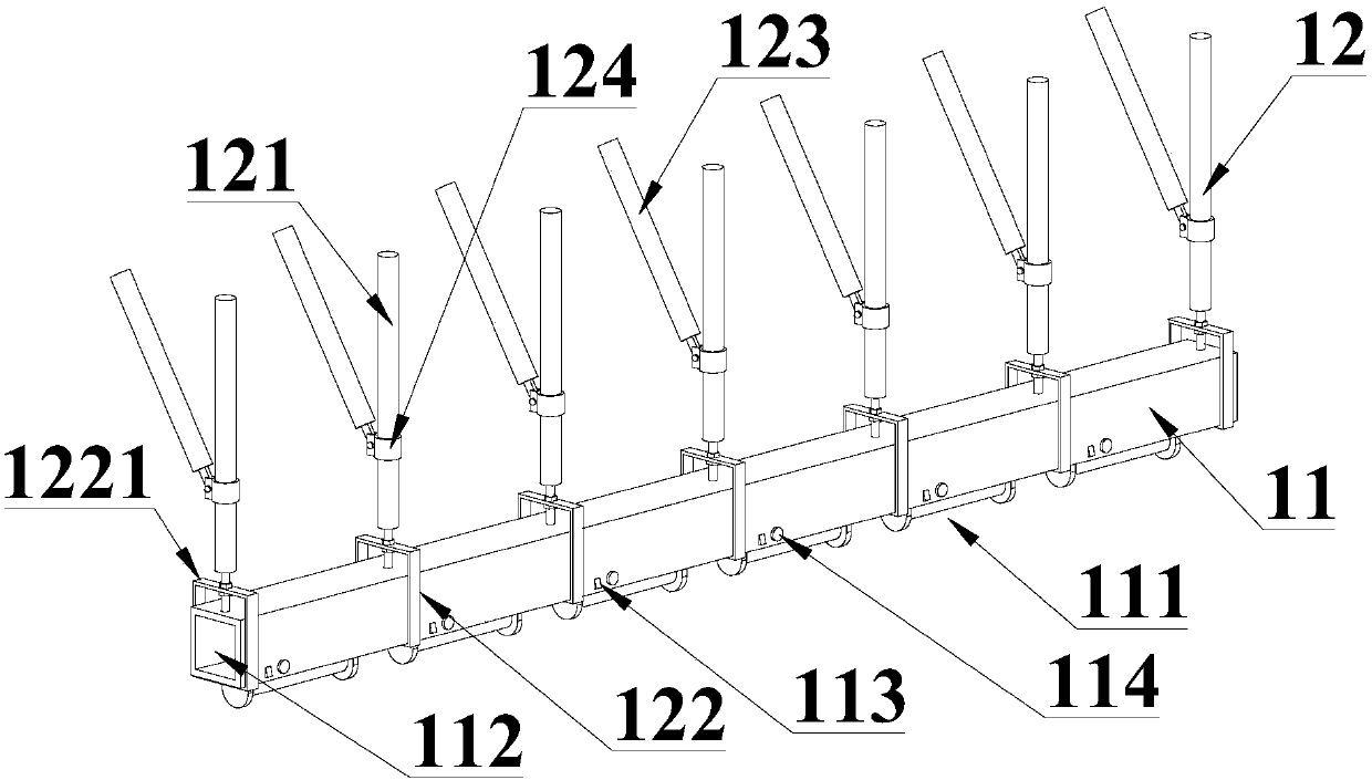
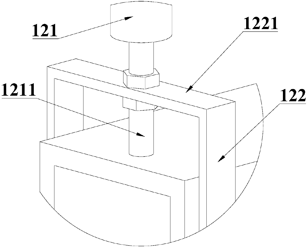
[0034] refer to figure 2 The lighting device 1 includes a lighting bracket 11 and a mounting frame 12. The bottom of the lighting bracket 11 is fixed with a plurality of lighting lamps 111 along the length direction, and the lighting bracket 11 is provided with a cable hole 112 that runs through the length direction. Pass through the cable hole 112 to supply power to the illuminating lamp 111 and other electrical equipment. The lighting bracket 11 is also provided with a lighting switch 113 corresponding to each lighting lamp 111, so as to individually adjust the opening and closing of each ...
Embodiment 2
[0045] refer to Figure 8 The difference between this embodiment and Embodiment 1 is that the support unit 211 is also provided with a sleeve 2114, the sleeve 2114 is a hollow circular platform structure, and the end of the sleeve 2114 with a smaller diameter is closed and connected to the supporting The ring 2112 is fixedly fitted, and the other end of the sleeve 2114 has an opening larger than the diameter of the column 2111 , and the sleeve 2114 is sleeved on the column 2111 . The steam pipe 221 passes through the support ring 2112. During the working process, the change of the position of the iron 22 will drive the steam pipe 221 to slide along the support ring 2112, and then drive the sleeve 2114 to rotate on the column 2111, thereby Reduce friction, reduce wear on steam pipe 221, and increase service life.
Embodiment 3
[0047] refer to Figure 9 The difference between this embodiment and Embodiment 1 is that the support unit 211 further includes a support rod 2113, the support rod 2113 is arranged on the column 2111, and the support rod 2113 is rotatably matched with the column 2111, The support ring 2112 is fixed on one end of the support rod 2113; the support rod 2113 is a bent rigid rod body. In Embodiment 1, since the column 2111 is fixed at a corner of the ironing station 21, when the iron 22 is far away from the column 2111, the steam pipe 221 will fall on the ironing station 21, affect normal work. By setting the curved support rod 2113, the support ring 2112 is closer to the center of the ironing station 21, preventing the steam pipe 221 from falling on the ironing station 21, which facilitates the operation.
PUM
 Abstract
Description
Claims
Application Information