
An adjustable punching module applied to a mold

An adjustable, mold technology, applied in the direction of forming tools, manufacturing tools, perforation tools, etc., can solve the problems of troublesome installation, high cost, long disassembly time, etc., and achieve the effect of cost saving and simple structure

Active Publication Date: 2019-01-08
江门市新会区益泓不锈钢制品有限公司
View PDF7 Cites 0 Cited by
  • Summary
  • Abstract
  • Description
  • Claims
  • Application Information

AI Technical Summary

Problems solved by technology

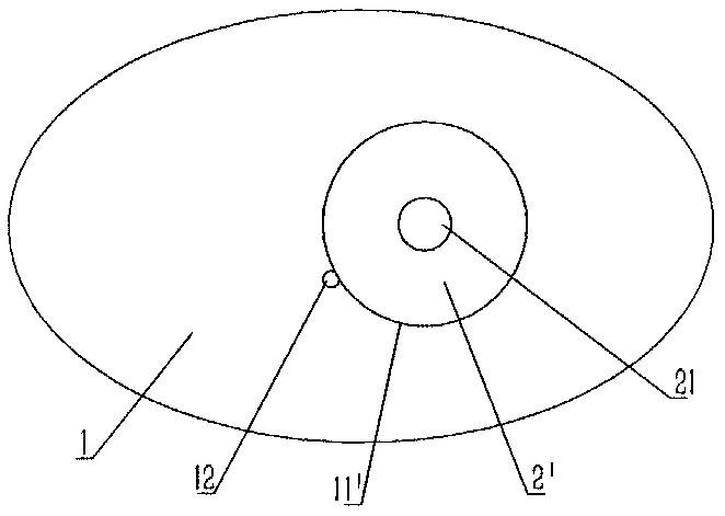
The installed structure of the embedded module of the original mold is as follows: figure 1 As shown, a circular socket 11' is formed on the substrate 1, and a small hole for destroying the socket is formed on the side wall of the socket. The embedded module generally adopts a cylindrical embedded module 2', and the cylindrical embedded module 2 '' diameter is slightly larger than the diameter of the socket 11', and then the cylindrical embedded module 2' is punched into the socket 11', but because the positioning accuracy of the punching hole on the stamping die is relatively high, and the cylindrical embedded module 2' Punching holes will inevitably have positional deviation. When the deviation is too large, only the cylindrical embedded module 2' can be punched out from the mold. The new cylindrical embedded module 2' is used, while the old cylindrical embedded module 2' can only be punched out. Can be scrapped, using this kind of embedded module is not only troublesome to install, but also takes a long time to disassemble, and the cost is high

Method used


Image

  • An adjustable punching module applied to a mold
  • An adjustable punching module applied to a mold
  • An adjustable punching module applied to a mold

Examples


Embodiment Construction

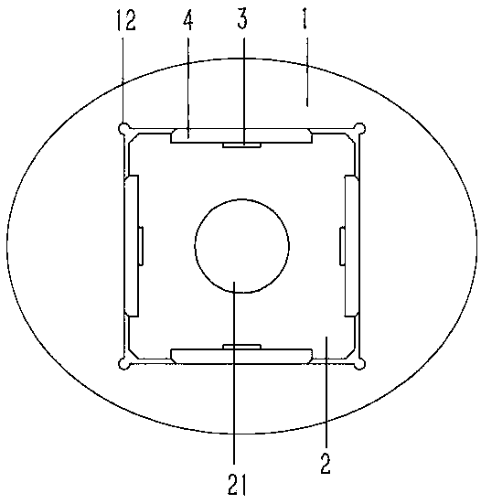
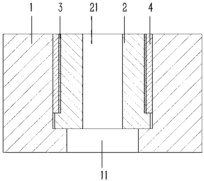
[0017] Example: see Figure 2 to 4 As shown, an adjustable punching module applied to a mold includes a base plate 1 of the mold. A rectangular stepped hole 11 is formed on the base plate 1, and a rectangular embedded module 2 is inserted into the stepped hole 11 of the base plate 1. The center of the module 2 is formed with a punching hole 21, the four corners of the stepped hole 11 of the substrate 1 are formed with arc-shaped grooves 12, the side wall of the embedded module 2 is formed with a rectangular recess 22, and the bottom surface of the recess 22 is formed with In the card slot 23, the permanent magnet block 3 is inserted and fixed in the card slot 23 of the embedded module 2, and the adjusting washer 4 is inserted in the recess 22 of the embedded module 2, and the two end surfaces of the adjusting gasket 4 respectively abut It leans on the inner wall of the stepped hole 11 of the base plate 1 of the embedded module 2 and the bottom surface of the recess 22 of the em...


PUM


Abstract

The invention discloses an adjustable punching die block applied to a die. The die block comprises a base plate of the die, a rectangular step hole is formed in the base plate, a rectangular embeddingdie block is inserted in the step hole of the base plate, a punching hole is formed in the center of the embedding die block, arc channels are formed in the four corners of the step hole of the baseplate, a rectangular concave table is formed on the side wall of the embedding die block, a clamping groove is formed in the bottom face of the concave table, a permanent magnet block is fixedly inserted in a clamping groove of the embedding die block, an adjusting gasket is inserted in the concave table of the embedding die block, the end faces of the two sides of the adjusting gasket abut against the inner wall of the step hole of the base plate of the embedding die block and the bottom face of the concave table of the embedding die block correspondingly, the adjustable punching die block issimple in structure, a punching debugging die block is provided, when the punching positioning position does not meet the position, the die block can be taken down, the adjusting gasket is ground andrepaired, the punching debugging die block is mounted, scrappage is avoided, and cost is saved.

Description

Technical field: [0001] The invention relates to the technical field of molds, and more specifically to an adjustable punching module applied to a mold. Background technique: [0002] At present, the punching hole matched with the punching knife on the punching die is generally formed on the embedded module, and then the embedded module is inserted into the base plate of the mold. The structure of the embedded module of the original mold after installation is as follows figure 1 As shown, a circular jack 11' is formed on the base plate 1, and a small hole is formed on one side wall of the jack to destroy the jack. The embedded module generally adopts a cylindrical embedded module 2', and a cylindrical embedded module 2 The diameter of ′ is slightly larger than the diameter of the socket 11 ′, and then the cylindrical embedded module 2 ′ is punched into the socket 11 ′, but because the positioning accuracy of the punching die on the punching die is higher, the cylindrical embedded...

Claims


Application Information

Patent Timeline
Patent Type & Authority Patents(China)
IPC IPC(8): B21D28/34B21D37/04
CPCB21D28/34B21D37/04
Inventor 杨勇
Owner 江门市新会区益泓不锈钢制品有限公司
Learn More