
Automobile engine maintenance device with lifting function

A technology of automobile engine and function, which is applied in the direction of lifting device, vehicle maintenance/repair, lifting frame, etc., and can solve problems such as inconvenient movement, inability to perform comprehensive maintenance, and reduced maintenance efficiency

Inactive Publication Date: 2018-02-27
桐乡市搏腾贸易有限公司
View PDF5 Cites 2 Cited by
  • Summary
  • Abstract
  • Description
  • Claims
  • Application Information

AI Technical Summary

Problems solved by technology

[0002] With the changes of the times and the continuous improvement of people's living standards, people's means of transportation are also constantly changing and upgrading. Now it is very common for people to use cars to travel when they go out. Because of a person's heart, the source of power, once the engine has a problem, the entire car cannot be used normally, so it needs to be repaired, but the general car engine is large in size and heavy, and it is inconvenient to move. For maintenance, it is necessary to use lifting equipment to lift the engine out and place it on the platform for maintenance. However, because the operating surface of a general platform is a solid plane, the part where the engine is supported on the platform is blocked, and it is impossible to carry out all-round maintenance. Lifting is required. The equipment helps the engine turn over on the platform, which will reduce the maintenance efficiency and take more time

Method used


Image

  • Automobile engine maintenance device with lifting function
  • Automobile engine maintenance device with lifting function
  • Automobile engine maintenance device with lifting function

Examples


Embodiment Construction

[0016] The technical solution of this patent will be further described in detail below in conjunction with specific embodiments.

[0017] Embodiments of the present patent are described in detail below, examples of which are shown in the drawings, wherein the same or similar reference numerals designate the same or similar elements or elements having the same or similar functions throughout. The embodiments described below by referring to the figures are exemplary and are only used for explaining the patent, and should not be construed as limiting the patent.

[0018] In the description of this patent, it is to be understood that the terms "center", "upper", "lower", "front", "rear", "left", "right", "vertical", "horizontal", The orientation or positional relationship indicated by "top", "bottom", "inner", "outer", etc. is based on the orientation or positional relationship shown in the drawings, and is only for the convenience of describing this patent and simplifying the des...


PUM


Abstract

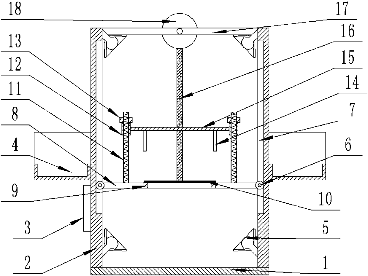
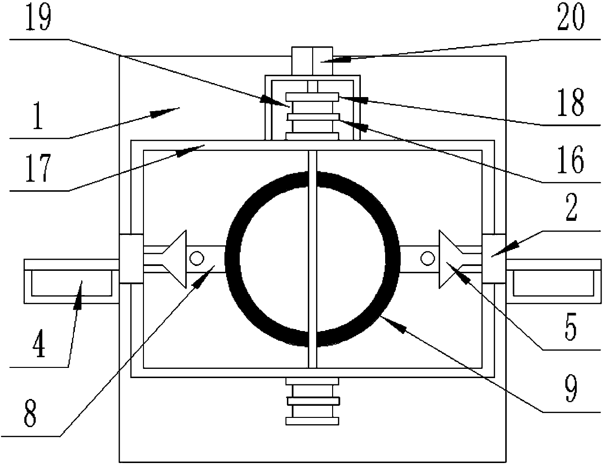
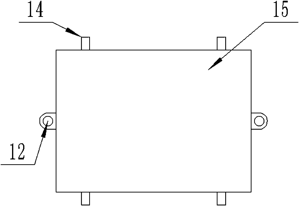
The invention provides an automobile engine maintenance device with a lifting function, and belongs to the field of automobile maintenance. The automobile engine maintenance device with the lifting function comprises a supporting plate and a reinforcing plate. Two supporting bars are vertically and fixedly connected to the midpoints of the left and right sides of the upper end face of the supporting plate correspondingly. A supporting ring is horizontally arranged between the supporting bars on the left and right sides of the supporting plate. The left side and the right side of the supportingring are horizontally and fixedly connected with connecting plates in the left-right direction correspondingly. According to the automobile engine maintenance device with the lifting function, the supporting ring is used for supporting and storing an engine so that a maintainer can repair the bottom of the engine from the lower side conveniently, and multidirectional maintenance is facilitated; arubber pad is used for increasing the friction force of the upper end face of the supporting ring so that the engine can be stably located on the supporting ring; and wheels on the connecting platesare combined with strip-shaped slideways, so that the supporting ring and the supporting bars are connected, the supporting ring can conveniently slide up and down along the strip-shaped slideways through the wheels and drives the engine supported by the supporting ring to slide up and down, and thus the maintainer can maintain the upper portion and the lower portion of the engine conveniently.

Description

technical field [0001] The invention relates to equipment related to automobile maintenance, in particular to an automobile engine maintenance device with lifting function. Background technique [0002] With the changes of the times and the continuous improvement of people's living standards, people's means of transportation are also constantly changing and upgrading. Now it is very common for people to use cars to travel when they go out. Because of a person's heart, the source of power, once the engine has a problem, the entire car cannot be used normally, so it needs to be repaired, but the general car engine is large in size and heavy, and it is inconvenient to move. For maintenance, it is necessary to use lifting equipment to lift the engine out and place it on the platform for maintenance. However, because the operating surface of a general platform is a solid plane, the part where the engine is supported on the platform is blocked, and it is impossible to carry out al...

Claims


Application Information

Patent Timeline
Patent Type & Authority Applications(China)
IPC IPC(8): B25H1/00B25H1/12B60S5/00B66F7/02B66F7/28
CPCB25H1/0007B25H1/12B60S5/00B66F7/02B66F7/28
Inventor 王晨
Owner 桐乡市搏腾贸易有限公司
Learn More