Method for achieving multi-image video combined display of commercial vehicle blind area

A realization method and multi-picture technology, applied to vehicle parts, optical observation devices, transportation and packaging, etc., can solve the problems of single, single display of alarm information and light, and less comprehensive information of auxiliary video images in blind spots, etc.

Inactive Publication Date: 2018-02-27
付宇
View PDF0 Cites 6 Cited by
  • Summary
  • Abstract
  • Description
  • Claims
  • Application Information

AI Technical Summary

Problems solved by technology

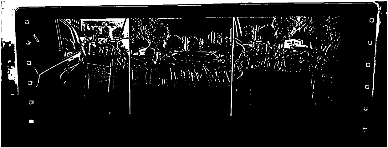
Passenger car blind spot auxiliary display screen and entertainment navigation screen are shared, and the functions of the two products will affect each other when users use them; at the same time, the existing blind spot auxiliary video images are all single-screen, and the combined video images of multiple cameras that meet visual habits cannot be displayed at one time , so that the comprehensive information of the blind spot assist video image that the driver sees on the entertainment screen at one time is very little
Existing passenger car BSD products only display alarm information on the left and right rearview mirrors in the form of flashing lights when the vehicle speed is higher than a certain speed.
Due to the particularity of commercial vehicle models, the blind spots of commercial vehicles are larger than those of passenger vehicles, but because of the professionalization of commercial vehicle drivers, fewer display screens are installed than those of passenger vehicles, or the rear view screen has a single function, and the application of new technologies is higher than that of passenger vehicles. Due to lag and other reasons, the existing commercial vehicle blind spot auxiliary products are basically blank
Existing buses are equipped with intelligent dispatching screens as standard. If the blind spot auxiliary display screen is shared with the intelligent dispatching screen, the functions of the two products will affect each other when users use them.

Method used


Image

  • Method for achieving multi-image video combined display of commercial vehicle blind area
  • Method for achieving multi-image video combined display of commercial vehicle blind area
  • Method for achieving multi-image video combined display of commercial vehicle blind area

Examples


Embodiment Construction

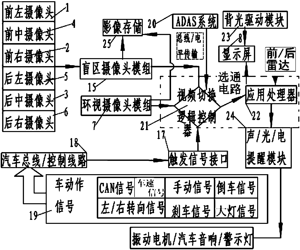
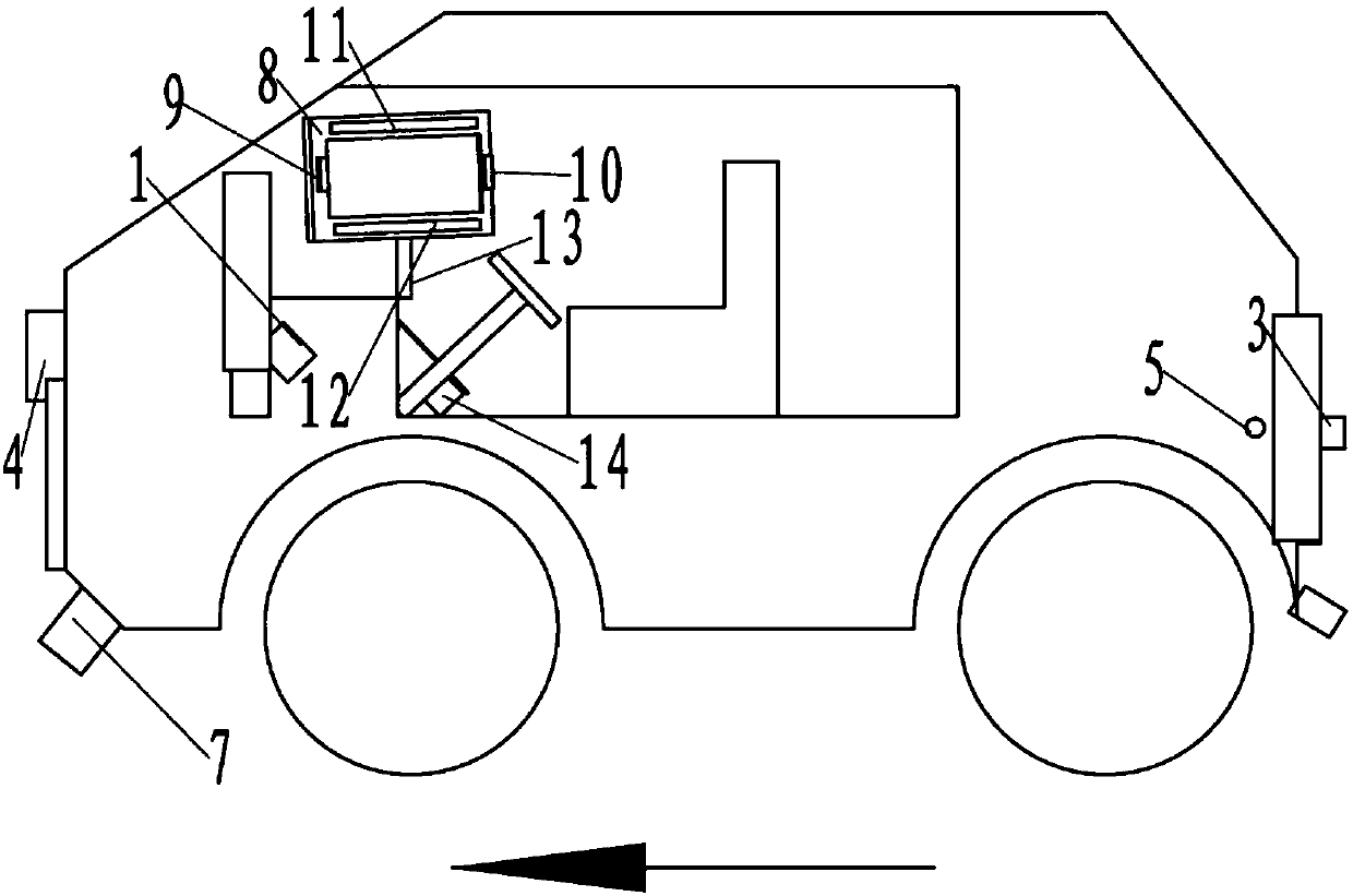
[0006] refer to Figure 1-17 shown, where in Figure 1-7 Among them, the vehicle-mounted system of commercial vehicles and trucks without blind spots in this embodiment includes an input unit, an application processor 22 electrically connected to the input unit, and an output unit electrically connected to the application processor 22; The blind spot camera module 15 of taking pictures, and the video switching logic controller 21 that input end is electrically connected with blind spot camera module 15 output ends;

[0007] The blind spot camera module 15 includes a front n-type camera system and / or a rear U-type camera system;

[0008] The output unit includes a display screen 8 for split-screen display or single-screen display of information captured by the blind spot camera module 15 , and the display screen 8 is electrically connected to the application processor 22 .

[0009] The present invention transmits the real-scene imaging information of the left front, right fro...


PUM


Abstract

The invention relates to a method for realizing combined display of multi-picture video in the blind area of ​​a commercial vehicle, which is implemented by means of a display screen, a blind area camera module, a video switching logic controller, an application processor, and a surround view camera module respectively installed on the vehicle ;The blind spot camera module includes a front left camera, a front right camera, a rear center camera, a front center camera, a rear left camera, and a rear right camera for respectively taking pictures of the corresponding viewing angle directions; including step 1, first, install the surround view on the car Camera module, then, according to the car model and the blind spot of looking around the camera module, adjust the angle of view of each camera in the blind area camera module, the blind area formed by the angle of view of each camera is covered by the blind area of ​​looking around; the present invention is reasonable in design, compact in structure and Easy to use.

Description

technical field [0001] The invention relates to a method for realizing multi-picture video combined display in blind spots of commercial vehicles. Background technique [0002] At present, the mainstream products for assisting driving in the blind spot of passenger cars using video imaging technology are 360-degree panoramic view, and blind spot assisting camera products installed in the left and right rearview mirrors and interior rearview mirrors. Because the 360-degree panoramic view has serious image distortion, the range of effective images is too short, and it does not conform to people's traditional visual habits. Even if users install the panoramic view product, the frequency of use is very low. Left, right and inner rear view blind spot products only solve part of the blind spots in the left and right rear areas of passenger cars. Passenger car blind spot auxiliary display screen and entertainment navigation screen are shared, and the functions of the two products ...

Claims


Application Information

Patent Timeline
Patent Type & Authority Applications(China)
IPC IPC(8): B60R1/00
CPCB60R1/00B60R2300/105B60R2300/303B60R2300/607B60R2300/802
Inventor 付宇付红强
Owner 付宇
Why Eureka
Try Eureka