
Tyndall phenomenon experiment device and experiment method thereof

A technology of experimental equipment and experimental methods, which is applied in the field of Tyndall phenomenon experimental equipment, can solve the problems of imprecise demonstration of Tyndall phenomenon, easy to mislead students and teachers, and achieve the effect of rigorous demonstration, intuitive understanding and high success rate

Inactive Publication Date: 2018-02-27
独山县青少年活动中心
View PDF3 Cites 0 Cited by
  • Summary
  • Abstract
  • Description
  • Claims
  • Application Information

AI Technical Summary

Problems solved by technology

[0003] To sum up: the existing technology has the disadvantage of not being rigorous in the demonstration of the Tyndall phenomenon and easily misleading students and teachers

Method used


Image

  • Tyndall phenomenon experiment device and experiment method thereof
  • Tyndall phenomenon experiment device and experiment method thereof
  • Tyndall phenomenon experiment device and experiment method thereof

Examples


Embodiment 1

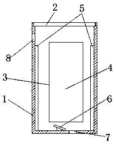
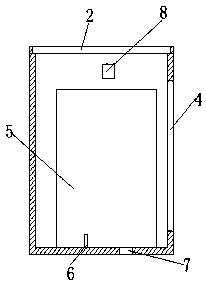
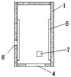
[0023] Example 1. A kind of Tyndall phenomenon experiment equipment, constitutes as Figure 1-3 As shown, it includes the box body 1, the head end of the box body 1 is provided with a box body cover 2, the front of the box body 1 is provided with an observation hole 3, and a transparent PC board 4 is arranged in the observation hole 3, and the left and right sides of the transparent PC board 4 have One side is arranged on the reflective mirror 5 on the inner wall of the box body 1, and the bottom of the box body 1 is provided with a laser pointer 6. Using the transparent PC board 4 to observe through the observation hole 3 not only isolates the influence of the external environment on the inside of the box body 1, but also makes the observed phenomenon more obvious.

[0024] The mirror surfaces of the reflectors 5 on the left and right sides of the transparent PC board 4 are arranged oppositely. When the laser pointer 6 of the present invention is actually installed, it has ...

Embodiment 2

[0035] Embodiment 2, the experimental equipment is the same as that of Embodiment 1, and the specific experimental steps are as follows: use a nebulizer to pass mist into the cabinet 1 through the mist hole 7, obtain the colloid formed by the mist and air in the cabinet 1, and turn on the laser pointer 6 , the experimental phenomenon can be observed through the transparent PC board 4 . The colloid can also be irradiated with a white torch or a white spotlight, and the experimental phenomenon can be observed vertically.

Embodiment 3

[0036] Embodiment 3, the experimental equipment is the same as that of Embodiment 1, and the specific experimental steps are as follows: use a dust generating device to feed dust into the casing 1 through the dust hole 8, obtain the colloid formed by dust and air in the casing 1, and turn on the laser pointer 6 , the experimental phenomenon can be observed through the transparent PC board 4 . The colloid can also be irradiated with a white torch or a white spotlight, and the experimental phenomenon can be observed vertically.


PUM


Abstract

The invention discloses a Tyndall phenomenon experiment device and an experiment method thereof. The Tyndall phenomenon experiment device comprises a box body (1), a box body cover (2) is arranged atthe head end of the box body (1), an observing hole (3) is formed in the front side of the box body (1), a transparent PC board (4) is arranged in the observing hole (3), a light-reflecting mirror (5)with one side arranged on the inner wall of the box body is arranged on the left side and the right side of the transparent PC board (4), and a laser pen (6) is arranged at the bottom of the box body(1). The Tyndall phenomenon experiment device can demonstrate multiple experiments related to a Tyndall phenomenon, teachers and students can visually understand the a Tyndall phenomenon and are notmisled, colloid and different colors of solutions are irradiated by changing different colors of laser pens, so that the Tyndall phenomenon is more rigorous in demonstration, and a whole demonstrationexperiment is simple in operation and high in success rate.

Description

technical field [0001] The invention relates to a teaching device for demonstrating the Tyndall phenomenon, in particular to a Tyndall phenomenon experimental device and an experimental method thereof. Background technique [0002] When a beam of light passes through the colloid, a bright "pathway" in the colloid can be observed from the vertical direction of the incident light. This phenomenon is called the Tyndall phenomenon. In middle school chemistry teaching, the Tyndall phenomenon of colloids is a compulsory content in middle school chemistry textbooks. In order to prove that the Tyndall phenomena of solutions and colloids are different, a true solution and a colloidal solution must be used for comparison. The true solution used in general textbooks It is a copper sulfate solution, which is a blue transparent solution. At the same time, ferric hydroxide colloid (red-brown) was used for comparison, and a red laser pointer was used. When a beam of light passed through t...

Claims


Application Information

Patent Timeline
Patent Type & Authority Applications(China)
IPC IPC(8): G09B23/24G09B23/22
CPCG09B23/24G09B23/22
Inventor 莫寿月何承丽伍丽周骏宏
Owner 独山县青少年活动中心
Learn More