A connection mechanism between the input shaft of a reducer and the output shaft of a drive motor

A technology for driving motors and connecting mechanisms, applied in electromechanical devices, electrical components, electric components, etc., can solve problems such as easy breakage, shaft jumping, loose connection between the output shaft of the driving motor and the input shaft of the reducer, etc., to achieve firm fixation, The concentricity is consistent and the effect of avoiding breakage

Active Publication Date: 2019-07-16
NINGBO HIRDEN IND CONTROL SYST
View PDF2 Cites 0 Cited by
  • Summary
  • Abstract
  • Description
  • Claims
  • Application Information

AI Technical Summary

Problems solved by technology

[0005] In the prior art, the clamping device is generally used to connect the output shaft of the drive motor and the input shaft of the reducer, and then bolts are used to lock the connecting flange; there are also some connection methods that are mostly traditional keyway fit; there are also some special places The connection method of key and tight double insurance will be adopted. The above connection methods need to use external connectors to realize the connection between the output shaft of the drive motor and the input shaft of the reducer, so that there is a gap between the output shaft of the drive motor and the input shaft of the reducer. The problem of loose connection between the two leads to a connection gap between the two, which makes the shaft jump when it is transmitted and is easy to break

Method used


Image

  • A connection mechanism between the input shaft of a reducer and the output shaft of a drive motor
  • A connection mechanism between the input shaft of a reducer and the output shaft of a drive motor
  • A connection mechanism between the input shaft of a reducer and the output shaft of a drive motor

Examples


Embodiment Construction

[0029] In order to make the technical means, creative features, goals and effects achieved by the present invention easy to understand, the following embodiments are combined with the accompanying drawings to elaborate on the present invention.

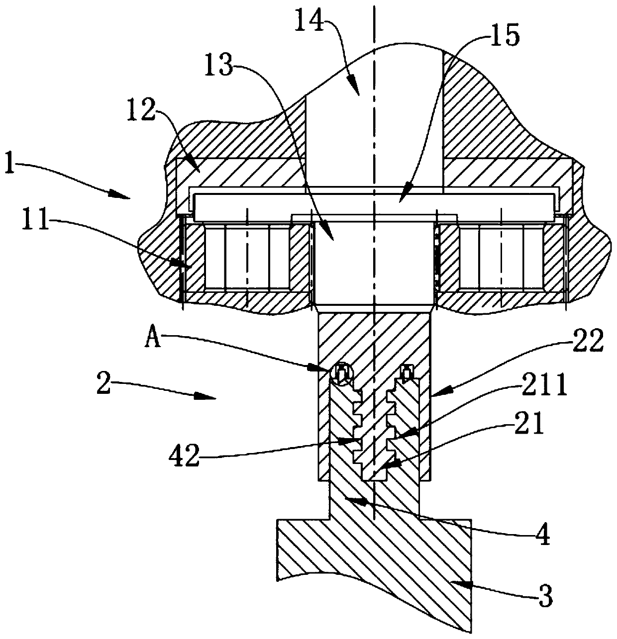
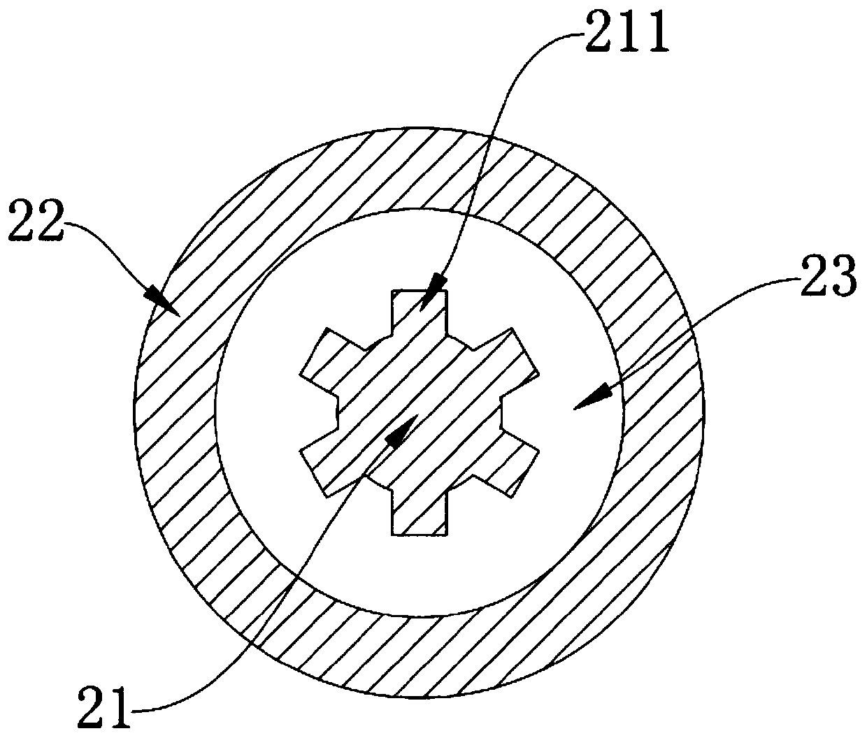
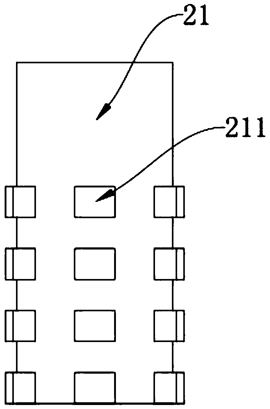
[0030] figure 1 For the partial sectional view of the present invention, please combine figure 1 , shows a connection mechanism between the input shaft 2 of the reducer 1 and the output shaft 4 of the drive motor 3, including the reducer 1 and the drive motor 3, the reducer 1 includes the input shaft 2, and the drive motor 3 includes the output shaft 4. The engagement between the input shaft 2 and the output shaft 4 can be that the input shaft 2 of the reducer 1 is set outside the output shaft 4 of the drive motor 3, or that the output shaft 4 of the drive motor 3 is set on the reducer The input shaft 2 of machine 1 is outside. In this embodiment, preferably, the input shaft 2 of the reducer 1 is sleeved outside the output shaft 4 o...


PUM


Abstract

The invention discloses a connection mechanism for an input shaft of a decelerator and an output shaft of a drive motor. The connection mechanism includes the decelerator and the drive motor. The decelerator includes the input shaft, the drive motor includes the output shaft, the input shaft of the decelerator sleeves the output shaft of the drive motor, and the input shaft and the output shaft are engaged. In the connection mechanism for the input shaft of the decelerator and the output shaft of the drive motor, the input shaft sleeves the output shaft and is engaged with the output shaft, and the auxiliary of external connection members is eliminated. Through this connection way, the input shaft of the decelerator is directly connected with the output shaft of the drive motor. The structure is simpler and firmer at the same time.

Description

technical field [0001] The invention relates to the technical field of connection mechanisms, in particular to a connection mechanism between an input shaft of a reducer and an output shaft of a driving motor. Background technique [0002] With the continuous development of the reducer industry, more and more enterprises have used the reducer, among which the reducer is widely used in industrial production due to its high precision and large transmission torque. When in use, the reducer is generally equipped with a power source, such as connecting with a DC motor, a single-phase motor, a synchronous motor and various three-phase asynchronous motors. When connecting, the concentricity of the input shaft of the reducer and the output shaft of the driving motor must be consistent. [0003] When the assembly concentricity between the reducer and the drive motor is guaranteed to be good, the input shaft of the reducer only bears the rotational force, and the operation will be smo...

Claims


Application Information

Patent Timeline
Patent Type & Authority Patents(China)
IPC IPC(8): H02K7/00
CPCH02K7/003
Inventor 王奇峰许海波
Owner NINGBO HIRDEN IND CONTROL SYST
Why Eureka
Try Eureka