
Robot clamp with clamping and material sucking functions

A robotic fixture and clamping mechanism technology, applied in the direction of chucks, manipulators, manufacturing tools, etc., can solve the problems of reducing product qualification rate, increasing labor costs, easy to scratch, etc., to improve the degree of automation, reduce labor costs, avoid The effect of scratches on the surface

Pending Publication Date: 2018-03-02
GUANGDONG LXD ROBOTICS CO LTD
View PDF6 Cites 5 Cited by
  • Summary
  • Abstract
  • Description
  • Claims
  • Application Information

AI Technical Summary

Problems solved by technology

[0002] At present, in the application of nail palletizing, because the oil has relatively high requirements on the surface, each layer must be separated by cardboard in the process of palletizing the oil to prevent the oil from being scratched; the existing technology is: The oil is transported and stacked by a general robot gripper, and the cardboard is placed manually; it has the following defects: 1. The traditional robot gripper needs to contact the surface of the oil during the clamping process, which makes it easy to scratch and reduces the quality of the product. Qualification rate; 2. Due to the low efficiency of manual operation, it directly affects the efficiency of palletizing; in addition, workers need to work non-stop, resulting in high labor intensity and certain potential safety hazards; moreover, arrangements need to be made during the palletizing work Workers arrange the cardboard, and the labor cost involved increases

Method used


Image

  • Robot clamp with clamping and material sucking functions
  • Robot clamp with clamping and material sucking functions
  • Robot clamp with clamping and material sucking functions

Examples


Embodiment Construction

[0019] The present invention will be further described below in conjunction with the accompanying drawings and embodiments, taking the palletizing work of oily resin Y as an example.

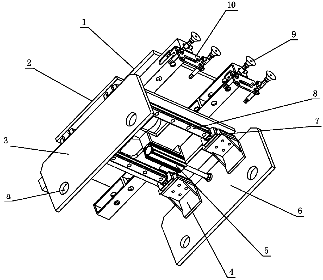
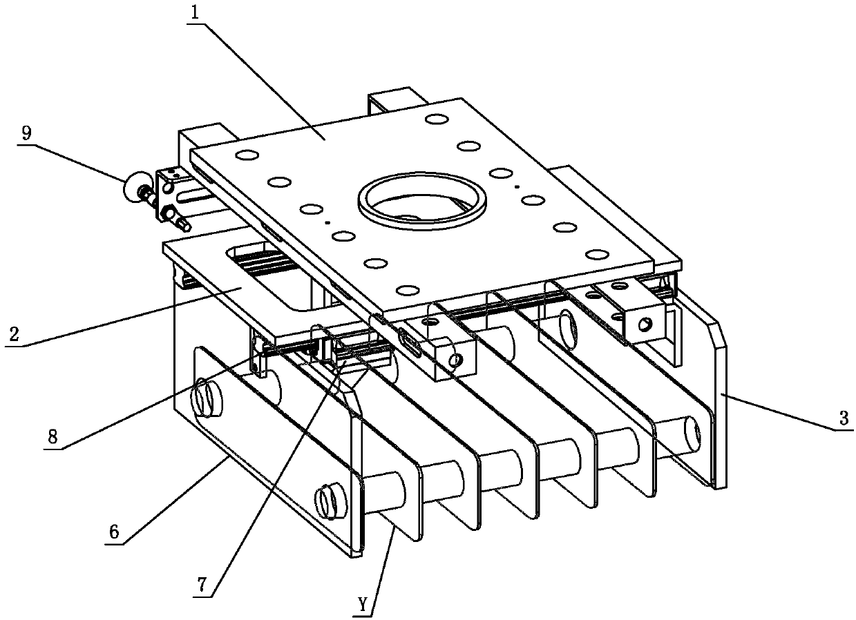
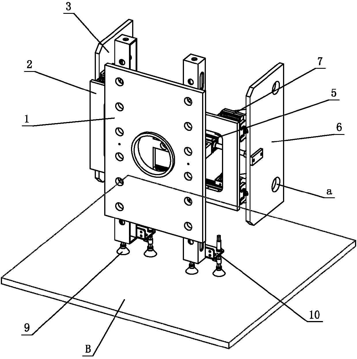
[0020] see Figure 1-Figure 6 , the robot fixture with clamping and suction functions is used to clamp the oil group composed of several oils Y. The robot fixture includes a fixture bracket connected to the robot through a flange. The fixture bracket is provided with a clamping mechanism and Suction mechanism; wherein, the clamping mechanism includes a first clamping plate 3, a second clamping plate 6 and a clamping drive assembly respectively arranged on the clamp bracket, and the clamping drive assembly drives the second clamping plate 6 relative to the clamp bracket Sliding back and forth to make the two clamping plates close to or far away from each other to achieve the effect of clamping the oil base Y. Since the two sides of the oil base Y are provided with convex points Y1, the first clam...


PUM


Abstract

The invention relates to a robot clamp with clamping and material sucking functions. The robot clamp comprises a clamp support connected with a robot through a flange, and a clamping mechanism and a material sucking mechanism are arranged on the clamp support; the clamping mechanism comprises a first clamping plate, a second clamping plate and a clamping driving assembly which are arranged on theclamp support, and the clamping mechanism drives the first clamping plate and / or the second clamping plate to do reciprocated sliding relative to the clamp support to enable the two clamping plates toget close to or be far away from each other; and the material sucking mechanism comprises a sucker arranged on the clamp support. The robot clamp is provided with the clamping mechanism and the material sucking mechanism at the same time, and therefore the robot clamp has the clamping and material sucking functions at the same time; by means of the clamp, oil heater clamping and paperboard placement can be completed, full-automatic stacking of oil heaters is achieved, and the equipment automatic degree, the system safety and the working efficiency are improved; and as the overall stacking process does not need worker participation, the labor intensity of workers is reduced, and the manpower cost is reduced.

Description

technical field [0001] The invention relates to the technical field of automation equipment manufacturing, in particular to a robot clamp with the functions of clamping and material suction. Background technique [0002] At present, in the application of nail palletizing, since the oil has relatively high requirements on the surface, each layer must be separated by cardboard in the process of palletizing the oil to prevent the oil from being scratched; the existing technology is: The oil is transported and stacked by a general robot gripper, and the cardboard is placed manually; it has the following defects: 1. The traditional robot gripper needs to contact the surface of the oil during the clamping process, which makes it easy to scratch and reduces the quality of the product. Qualification rate; 2. Due to the low efficiency of manual operation, it directly affects the efficiency of palletizing; in addition, workers need to work non-stop, resulting in high labor intensity a...

Claims


Application Information

Patent Timeline
Patent Type & Authority Applications(China)
IPC IPC(8): B65G61/00B25J15/08B25J15/06
CPCB65G61/00B25J15/0616B25J15/08
Inventor 毛俊伟林育锐胡尕磊
Owner GUANGDONG LXD ROBOTICS CO LTD
Learn More