Diaphragm valve as well as fluid conveying equipment formed by diaphragm valve and conveying method thereof

A technology of fluid conveying and diaphragm valve, applied in the direction of diaphragm valve, diaphragm, mechanical equipment, etc., can solve the problems of high cost, high failure rate, complex structure, etc.

Pending Publication Date: 2018-03-02
新疆巨盛龙环保设备有限公司
View PDF5 Cites 3 Cited by
  • Summary
  • Abstract
  • Description
  • Claims
  • Application Information

AI Technical Summary

Problems solved by technology

[0003] Therefore, the existing diaphragm valve needs to be equipped with complex au

Method used


Image

  • Diaphragm valve as well as fluid conveying equipment formed by diaphragm valve and conveying method thereof
  • Diaphragm valve as well as fluid conveying equipment formed by diaphragm valve and conveying method thereof
  • Diaphragm valve as well as fluid conveying equipment formed by diaphragm valve and conveying method thereof

Examples


no. 1 example

[0046] The first embodiment: a fluid conveying device composed of one diaphragm valve.

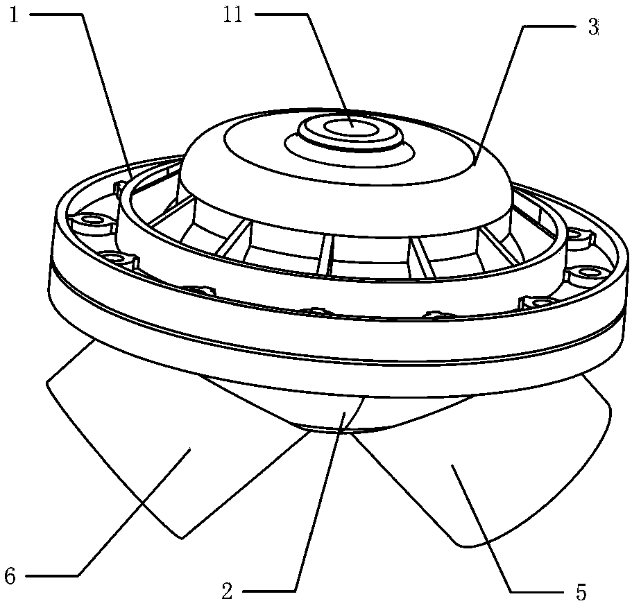
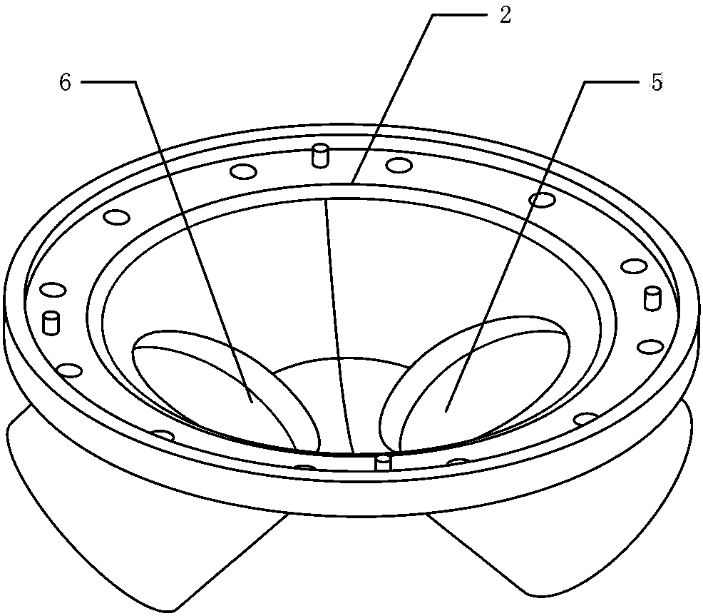
[0047] Such as Figure 5 , 6 As shown, the valve body inlet 5 is connected to the toilet, and the valve body outlet 6 is connected to the vacuum sewage tank.

[0048] The valve cover 3 is connected to the vacuum dirt collection tank through the electromagnetic valve 7, that is, the first passage 8 of the electromagnetic valve is connected to the valve cover 3, and the second passage 9 of the electromagnetic valve is connected to the second passage 9 of the electromagnetic valve. The third channel 10 communicates with the atmosphere and the vacuum collection tank respectively.

[0049]The fluid conveying equipment is divided into three working states:

[0050] (1) In the case of no need to transport fluid, the solenoid valve 7 is not energized, such as Figure 5 Said, the position of the electromagnetic valve slider 12 is at A, the negative pressure cannot enter the inner cavity of the ...

no. 2 example

[0053] The second embodiment: a fluid conveying device composed of two diaphragm valves.

[0054] Such as Figure 7 As shown, the valve body inlet 5 is connected to the valve body outlet 6', that is, the two diaphragm valves are connected together. In this way, if solid residues are deposited on the bottom of the individual diaphragm valves, causing the diaphragms to not seal the inlet and outlet of the valve body tightly, the diaphragm valves as a whole can still achieve good opening and closing effects.

[0055] The fluid conveying equipment is divided into three working states:

[0056] (1) In the case of no need to transport fluid, the solenoid valve 7 is not energized, such as Figure 5 Said, the position of the electromagnetic valve slider 12 is at A, the negative pressure cannot enter the inner cavity of the diaphragm valve 1 and the diaphragm valve 1', the inner cavity of the valve is connected with the atmosphere, and the inner cavity of the valve is in a normal pre...


PUM


Abstract

The invention discloses a diaphragm valve as well as fluid conveying equipment formed by the diaphragm valve and a conveying method thereof, and belongs to the field of valves and sanitary and bathroom equipment. The diaphragm valve comprises a valve body, a valve cover and a diaphragm, wherein the valve cover, the diaphragm and the valve body are sequentially connected; a cavity is formed betweenthe valve body and the valve cover; the diaphragm is arranged in the cavity; under a first state, the diaphragm covers the valve body; and under a second state, an isolating space is formed between the diaphragm and the valve body. The diaphragm valve solves the problems that an existing diaphragm valve is complex in structure, is high in cost and is high in fault rate, and has the advantages ofbeing flexible in opening and tight in sealing. The invention further discloses fluid conveying equipment formed by the diaphragm valve and the conveying method thereof.

Description

technical field [0001] The invention relates to a valve and sanitary equipment thereof, in particular to a diaphragm valve, a fluid conveying device composed of the diaphragm valve and a conveying method thereof. Background technique [0002] A diaphragm valve is a valve that is opened and closed by the deformation of a flexible diaphragm (such as a rubber diaphragm). Diaphragm valves can be controlled by cylinders, etc., but additional cylinders, etc. need to be provided; or, diaphragm valves can also be controlled pneumatically, but in this case, springs, pull rods, etc. need to be provided to reset the diaphragm valves. [0003] Therefore, the existing diaphragm valve needs to be provided with complex auxiliary mechanisms, resulting in complex structure, high cost and high failure rate. Contents of the invention [0004] In view of this, the object of the present invention is to provide a diaphragm valve with simple structure, low cost and low failure rate. [0005] T...

Claims


Application Information

Patent Timeline
IPC IPC(8): F16K7/17F16K51/02E03C1/12E03C1/122
CPCF16K7/17F16K51/02E03C1/12E03C1/1222
Inventor 蔡贾松
Owner 新疆巨盛龙环保设备有限公司
Why Eureka
Try Eureka