A wall-attached air device for preventing high-temperature corrosion of boiler water-cooled walls

A wall-attached wind and water-cooled wall technology, applied in the field of boilers, can solve problems such as the influence of combustion in the furnace, large air consumption, and easy burnout of nozzles, and achieve the effects of reducing high-temperature corrosion, reducing investment costs, and reducing the concentration of reducing atmosphere

Active Publication Date: 2019-08-02
XIANGTAN UNIV
View PDF4 Cites 0 Cited by
  • Summary
  • Abstract
  • Description
  • Claims
  • Application Information

AI Technical Summary

Problems solved by technology

The main problems of the method of extending the nozzle into the furnace to supply air are: ①The pressure of the secondary air is low, the rigidity is poor, the distance of flowing along the water wall is short, and the air consumption for forming the water wall covering the air film layer is large, which is harmful to the furnace. Internal combustion and boiler operation have a great influence; ②The temperature of the secondary air passing through the nozzle is high, and the single secondary air is cooled, the cooling effect of the nozzle is poor, and the nozzle is easy to burn out
The main problems of opening a large number of small holes through the fins of the water-cooled wall and supplying air perpendicular to the water-cooled wall surface are: ① When the secondary air is sprayed into the furnace perpendicular to the water-cooled wall surface, it will be injected deep into the furnace, which will affect the combustion in the furnace 2) To form a uniform protective gas film near the water wall, a large number of small holes need to be opened, the air consumption is large, and the combustion in the furnace is greatly affected, and a large wall-mounted bellows needs to be arranged, which requires a large investment
[0004] By searching the prior art, it is found that there is no method or device that can effectively solve the above problems

Method used


Image

  • A wall-attached air device for preventing high-temperature corrosion of boiler water-cooled walls
  • A wall-attached air device for preventing high-temperature corrosion of boiler water-cooled walls

Examples


Embodiment Construction

[0020] The present invention is further elaborated below in conjunction with accompanying drawing.

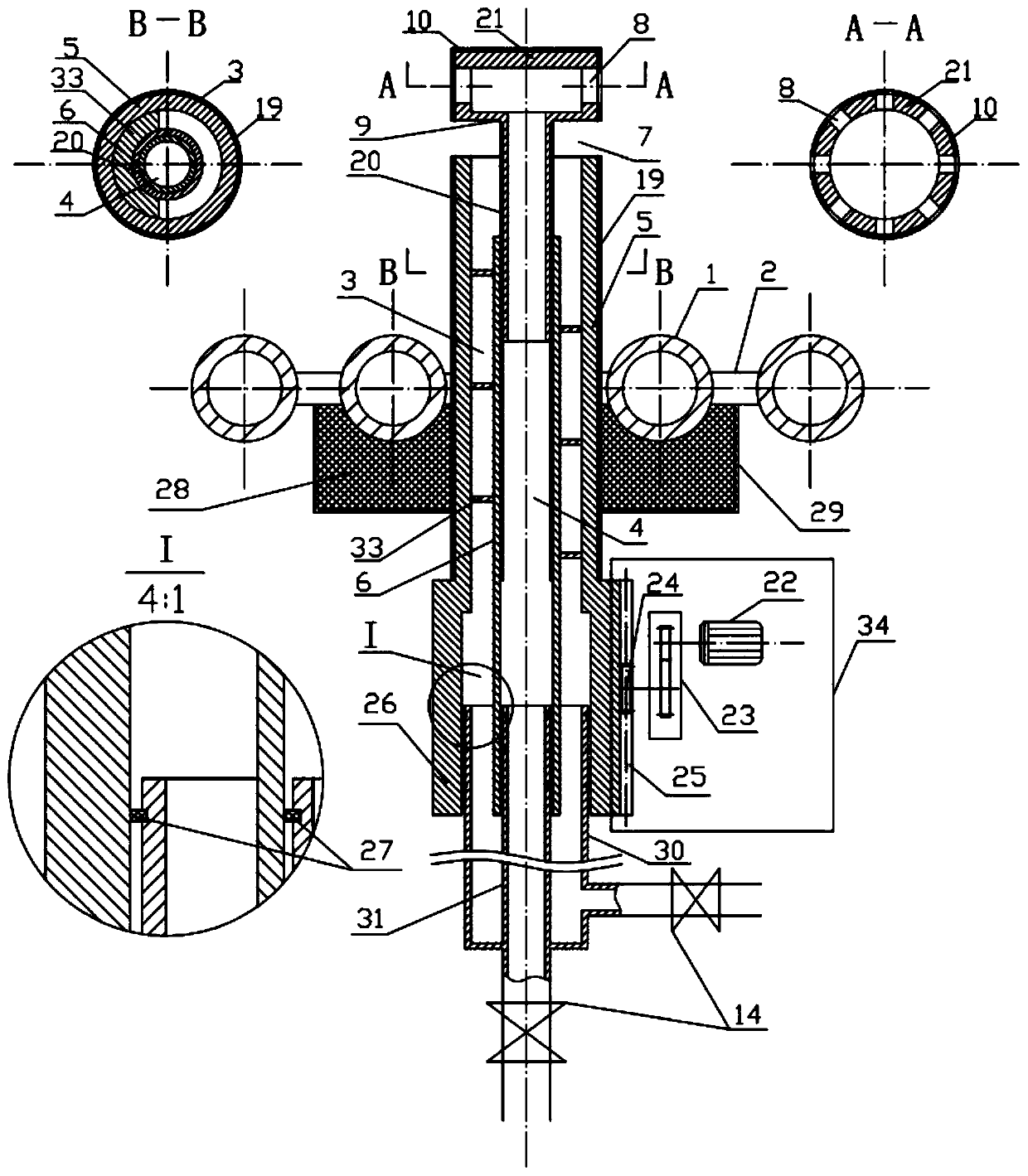
[0021] figure 1 Provided is a structural schematic diagram of the wall-attached air unit device for preventing high-temperature corrosion of the boiler water wall according to the present invention. The wall-attached air unit device is composed of a ventilation sleeve 13 , an axial adjustment device 34 , a sealing device 35 , a secondary air nozzle 9 and a connecting sleeve 32 . The ventilation casing is composed of a central secondary air pipe 6, a compressed air outer pipe 5, a spiral baffle 33, and a zirconia ceramic heat-insulating pipe 10 threaded on the compressed air outer pipe 5. The hole formed by the bending of the water wall tube extends into the furnace; the central secondary air passage 4 is surrounded by the inner wall of the central secondary air pipe 6, and the compressed air passage 3 is formed by the inner wall of the compressed air outer pipe 5 and the outer...


PUM


Abstract

A near-wall attaching apparatus is composed of: patent unit apparatuses, a linking wind pipe and a measurement and control system. The patent unit apparatus is composed of a ventilating sleeve tube, alinking sleeve tube, a spiral baffle plate, a sealing device, a secondary wind spray nozzle, a zirconia ceramic heat insulation disk, a zirconia ceramic heat insulation pipe, an adjustment valve, anaxial adjustment device, etc. A connection pipe and a bottom disk of the secondary wind spray nozzle are respectively in threaded connection with the ventilating sleeve tube and the zirconia ceramic heat insulation bottom disk. A plurality of secondary wind mouths are formed in the circumference of the bottom disk. The zirconia ceramic heat insulation pipe sleeves the outer pipe of the ventilatingsleeve tube, wherein the outlet of the zirconia ceramic heat insulation pipe and the bottom disk of the secondary wind spray nozzle form a compressed air nozzle. The air nozzle sprays a double-layerair film which separates furnace gas and the water wall, so that the water wall has the function of preventing high temperature corrosion. By means of pre-adjustment of the secondary wind spray nozzle, adjustment of the adjustment valve and axial adjustment of the patent unit apparatuses, the near-wall wind apparatus has good parameter adjustable performance and adaptability. Due to the heat insulation disk and the heat insulation pipe, the secondary wind and compressed air achieve double cooling, wherein the secondary wind spray nozzle is detachable, so that anti-burning and replaceable features of the parts in the boiler are achieved. The number of the patent unit apparatuses can be changed according to volume of the boiler.

Description

technical field [0001] The invention belongs to the technical field of boilers, and in particular relates to a wall-attached wind device for preventing high-temperature corrosion of boiler water walls. Background technique [0002] In the case of constant coal quality, the main factors affecting the high temperature corrosion of boiler water wall are: 1. The atmosphere near the water wall surface; 2. The temperature of the water wall tube wall; 3. The material of the water wall tube. In order to reduce coal consumption, the unit parameters have been getting higher and higher in recent years, and the temperature of the water-cooled wall tube wall has also increased; with the strong promotion of the national energy-saving and emission-reduction policy, more and more boilers adopt low-nitrogen combustion technology, and the graded low-nitrogen Combustion technology is easy to form a strong reducing atmosphere near the water wall, which makes the problem of high temperature corr...

Claims


Application Information

Patent Timeline
Patent Type & Authority Patents(China)
IPC IPC(8): F23C7/02F23L9/00F23M5/08
CPCF23C7/02F23C2900/06041F23L9/00F23M5/085
Inventor 徐顺生赵冬勇周学平廖利民傅国要王军梅于远友刘乐乐刘小宇龙绪功赵鹏飞贺家臻罗洁黄日升叶为标王志奇夏小霞刘炎桃裴斐石黎徐泉华
Owner XIANGTAN UNIV
Why Eureka
Try Eureka