
DC circuit breaker based on serial-in capacitor and DC fault handling strategy thereof
A technology of DC circuit breakers and capacitors, applied in the field of DC circuit breakers and their DC fault handling strategies, can solve the problems of large size, high cost, and difficult power grids to be widely used, and achieve low steady-state operation losses, lower investment costs, and reduced The effect of investment cost
- Summary
- Abstract
- Description
- Claims
- Application Information
AI Technical Summary
Problems solved by technology
Method used
Image

Examples
Embodiment Construction
[0024] In order to describe the present invention more specifically, the technical solutions of the present invention will be described in detail below in conjunction with the accompanying drawings and specific embodiments.
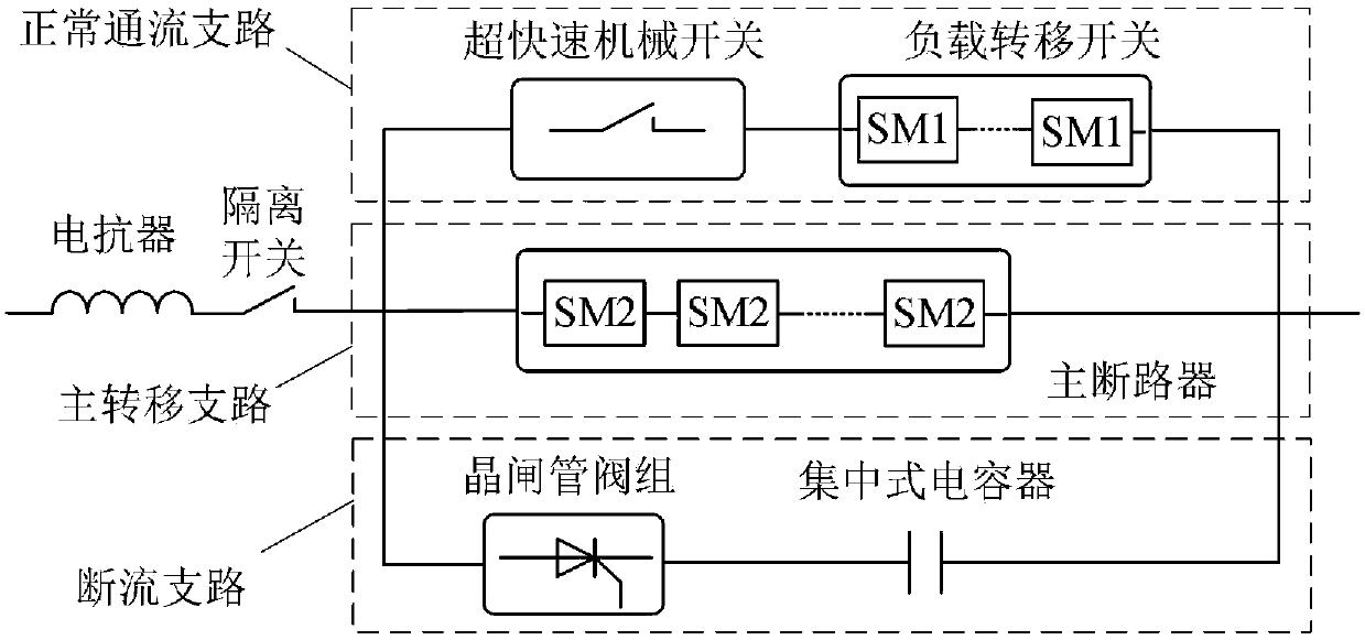
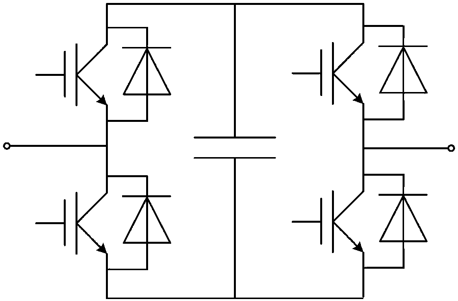
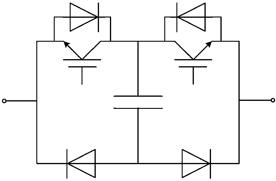
[0025] Such as figure 1 As shown, the DC circuit breaker of the present invention based on capacitors in series includes a normal flow branch, a main transfer branch, a cutoff branch, a reactor and a disconnector, wherein: the normal flow branch, the main transfer branch and the breaker The three flow branches are connected in parallel, one end of the parallel connection is connected to the DC line, and the other end is connected to one end of the isolating switch; the other end of the isolating switch is connected to one end of the reactor; the other end of the reactor is connected to the converter station.
[0026] The normal flow branch includes an ultra-fast mechanical switch and a load transfer switch, where the ultra-fast mechanical switch and load ...
PUM
 Abstract
Description
Claims
Application Information