Overvoltage protection circuit, charging circuit and related methods and terminal equipment

An overvoltage protection circuit and charging circuit technology, applied in safety/protection circuits, circuit devices, battery circuit devices, etc., can solve problems such as easy overvoltage burnout

Active Publication Date: 2018-03-02
MEIZU TECH CO LTD
View PDF4 Cites 2 Cited by
  • Summary
  • Abstract
  • Description
  • Claims
  • Application Information

AI Technical Summary

Problems solved by technology

[0004] The embodiment of the present invention provides an overvoltage protection circuit, a charging circuit, a related method, and a terminal device, which are used to solve the problem that the electronic components in the battery power supply network of the existing terminal equipment are easily damaged by overvoltage during battery charging. question

Method used


Image

  • Overvoltage protection circuit, charging circuit and related methods and terminal equipment
  • Overvoltage protection circuit, charging circuit and related methods and terminal equipment
  • Overvoltage protection circuit, charging circuit and related methods and terminal equipment

Examples


Embodiment 1

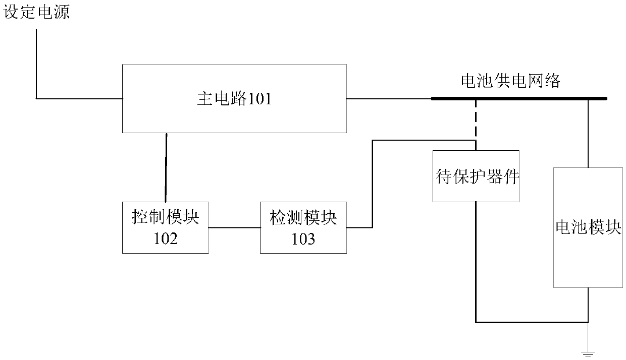
[0050] Embodiment 1 of the present invention provides an overvoltage protection circuit, specifically, as figure 1 As shown, it is a schematic structural diagram of the overvoltage protection circuit in the embodiment of the present invention, which may include a main circuit 101, a control module 102 and a detection module 103. The input terminal of the main circuit 101 is connected to the set power supply, and the output terminal Connected to a battery powered network where:

[0051] The detection module 103 can be used to detect the voltage value of the device to be protected in the battery power supply network;

[0052] The control module 102 is configured to send a set control signal to the main circuit 101 if it is determined that the voltage value of the device to be protected is not lower than a set voltage threshold;

[0053] The main circuit 101 can be configured to convert the electric energy provided by the set power supply in response to the set control signal, and...

example 1

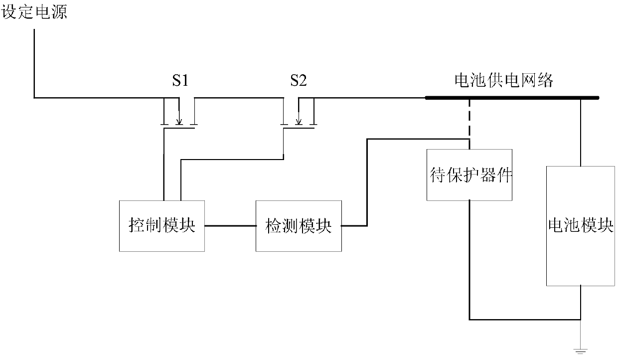
[0068] like image 3 As shown, it is a possible structural diagram of the overvoltage protection circuit provided in this embodiment, the power conversion module includes a switch S1, and the voltage stabilization module includes a switch S2.

[0069] During the battery charging process, the application processor in the terminal device can control and set the power supply, such as a power adapter, according to the voltage value of the battery cell of the battery module, and the output voltage range is a direct current with an appropriate voltage value. At this time, the equivalent impedance of the switch tube S1 and the switch tube S2 is small, therefore, the voltage value of the direct current output by the overvoltage protection circuit is closer to the appropriate voltage value.

[0070] The detection module detects the voltage value of the device to be protected in the battery-powered network in real time, and when the control module determines that the voltage value of th...

example 2

[0072] like Figure 4 As shown, it is another possible structural diagram of the overvoltage protection circuit provided in this embodiment. The power conversion module includes a switch tube S1, a switch tube S3, a switch tube S4, a switch tube S5, a capacitor C1, and a capacitor C2 , the connection relationship between them is shown in the figure, and will not be repeated here; the voltage stabilizing module includes a switch tube S2.

[0073] During the battery charging process, the application processor in the terminal device can control and set the power supply, such as a power adapter, according to the voltage value of the battery cell of the battery module, and the output voltage range is a direct current with an appropriate voltage value. The control module controls the conduction and disconnection of the switch tube S1, the switch tube S3, the switch tube S4 and the switch tube S5, so that the first stage of charging the capacitor C1 and the capacitor C2 connected in ...


PUM


Abstract

The invention provides an overvoltage protection circuit, a charging circuit and related methods and terminal equipment. The voltage value of a device to be protected in a battery power supply networkcan be detected in the battery charging process. If the voltage value of the device to be protected is ensured not to be lower than the preset voltage threshold, the voltage amplitude of the direct current supplied to the battery power supply network can be reduced according to the preset step and the objective of stabilizing the voltage of the device to be protected to be lower than the upper limit of the bearable voltage can be achieved so that the problem that the electronic parts and components in the battery power supply network are liable to be burned by overvoltage in the battery charging process can be avoided and the charging efficiency can be ensured as much as possible.

Description

technical field [0001] The present invention relates to the technical field of charging, in particular to an overvoltage protection circuit, a charging circuit, a related method and a terminal device. Background technique [0002] More and more terminal devices, such as smartphones, use fast charging to charge batteries. The charging current of the fast charging method is relatively large, such as 5A or even greater; and due to the impedance of the charging path, there are large differences in the voltage at different positions of the charging path during the battery charging process, such as the voltage of the battery cell of the battery module and There is a certain voltage difference between the voltage of the battery connector and the output voltage of the charging chip. In addition, various electronic components in the terminal equipment are connected to different positions of the charging path through the battery-powered network. Different electronic components have d...

Claims


Application Information

Patent Timeline
Patent Type & Authority Applications(China)
IPC IPC(8): H02J7/00
CPCH02J7/0077H02J7/0029Y02E60/10
Inventor 易鹏程
Owner MEIZU TECH CO LTD
Why Eureka
Try Eureka