Slurry soaking device

A technology for dipping and driving devices, which is applied in the field of dipping devices, can solve problems such as limited stirring efficiency, low stirring efficiency, and inability to handle, so as to avoid the loss of pulp, improve work efficiency, and improve the effect of stirring

Inactive Publication Date: 2018-03-06
东营腾云精铸设备有限责任公司
View PDF8 Cites 1 Cited by
  • Summary
  • Abstract
  • Description
  • Claims
  • Application Information

AI Technical Summary

Problems solved by technology

[0003] However, in the actual operation process, once the slurry dipping machine stops due to external factors such as power failure or equipment failure, the slurry powder in the round tube is easy to settle. Since the current scrapers are all L-shaped plate structures, they can be used in normal operation. However, once it settles, due to the large resistance, the slurry tank cannot be started, and even continuous start-up causes the motor to burn out. Big waste, if you encounter expensive special mixed pulp powder, it will definitely cause huge losses
[0004] In a utility model patent (CN 203936335 U), a kind of pulping machine is disclosed. In order to solve the problem that it takes a long time for the pulping machine to turn again after stopping, a stirring blade is arranged on the scraper. Although the stirring efficiency can be improved during work, there are great defects in this scheme. After a long time of precipitation due to power failure, the stirring cannot be carried out at all, and the larger stirring blades increase the corresponding resistance and start-up. Difficulty, poor adaptability to different slurries, and limited mixing efficiency
[0005] In a utility model patent (CN205996115U), a kind of pulp dipping machine discloses a technical scheme, which has a base, a pulp bucket, a column and a driving device, and when the pulp bucket stops running, the stirring blade can be moved by the hand wheel on the column. Longitudinal movement prevents the mixing blade from being solidified, but it cannot solve the problems of alleviating the solidification of the slurry powder and cleaning the solidification of the slurry powder, which will inevitably cause waste and low mixing efficiency

Method used


Image

  • Slurry soaking device
  • Slurry soaking device
  • Slurry soaking device

Examples


Embodiment Construction

[0022] In order to make the purpose, technical solutions and advantages of the embodiments of the present invention clearer, the technical solutions in the embodiments of the present invention will be clearly and completely described below in conjunction with the drawings in the embodiments of the present invention. Obviously, the described embodiments It is a part of embodiments of the present invention, but not all embodiments. The components of the embodiments of the invention generally described and illustrated in the figures herein may be arranged and designed in a variety of different configurations. Accordingly, the following detailed description of the embodiments of the invention provided in the accompanying drawings is not intended to limit the scope of the claimed invention, but merely represents selected embodiments of the invention. Based on the embodiments of the present invention, all other embodiments obtained by persons of ordinary skill in the art without mak...


PUM


Abstract

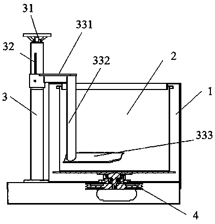
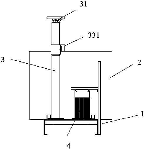
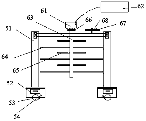
The invention discloses a slurry soaking device which comprises a slurry soaking machine and a slurry soaking auxiliary machine used cooperatively with the slurry soaking machine, wherein the slurry soaking machine comprises a machine seat, a vertical column, a slurry barrel and a driving device; the slurry barrel is arranged on the machine seat; the stirring barrel is driven by the driving deviceto rotate; the vertical column is arranged on one side of the machine seat; a lifting handle, a lifting rod and a stirring device are arranged on the vertical column; the stirring device comprises alifting flat plate, a supporting column and a stirring blade; and the slurry soaking auxiliary machine comprises a bracket and an auxiliary stirrer movably arranged on the bracket, and is applied to auxiliary stirring of slurry. Compared with the prior art, the slurry soaking device disclosed by the invention makes use of the liftable stirring blade; when a fault occurs, the blade rises up to avoid an equipment accident caused by extremely high resistance during secondary stirring; the slurry soaking auxiliary machine can be applied to auxiliary stirring when equipment is faulted or power fails, so that slurry loss caused by sedimentation and solidification of slurry powder within relatively short time is avoided; and after the fault is solved, production can be quickly recovered, and theworking efficiency is improved.

Description

technical field [0001] The invention relates to the field of precision casting equipment, in particular to a slurry dipping device. Background technique [0002] At present, the slurry dipping equipment used in the shell making process of investment casting mainly adopts the rotary scraper type slurry dipping machine, which mainly includes a circular slurry bucket, the bottom of which is connected with a rotary drive device, and a scraper is installed inside. , the circular slurry tank is filled with slurry. When the shell mold is dipped in slurry, the entire mold shell is immersed in the slurry, and the circular slurry is driven to rotate through the optional drive device at the bottom. At the same time, the circular slurry is Stir in the barrel to realize the operation of dipping the mold shell. [0003] However, in the actual operation process, once the slurry dipping machine stops due to external factors such as power failure or equipment failure, the slurry powder in t...

Claims


Application Information

Patent Timeline
Patent Type & Authority Applications(China)
IPC IPC(8): B22C23/02
CPCB22C23/02
Inventor 耿同新耿同伟李文荣刘强
Owner 东营腾云精铸设备有限责任公司
Why Eureka
Try Eureka