
Angle-sensor-based fan head rotating angle adjusting structure and method

An angle sensor and angle adjustment technology, which is applied in the direction of machines/engines, components of pumping devices for elastic fluids, instruments, etc., can solve problems such as waste of wind power, large fan swing angle, and inflexibility

Pending Publication Date: 2018-03-06
XINYI HUIMEI ELECTRICAL APPLIANCES
View PDF6 Cites 1 Cited by
  • Summary
  • Abstract
  • Description
  • Claims
  • Application Information

AI Technical Summary

Problems solved by technology

The above-mentioned swing structure is not flexible enough in use, sometimes only one or two people blow the fan, but the swing angle of the fan is too large, most of the time it is blowing in a place where there is no one, wasting the wind power

Method used


Image

  • Angle-sensor-based fan head rotating angle adjusting structure and method

Examples


Embodiment 1

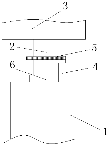
[0017] like figure 1 As shown, the angle sensor-based fan head rotation angle adjustment structure of this embodiment includes a fan bracket 1 and a fan head 3 mounted on the fan bracket 1 through a rotating shaft 2 (the rotating shaft 2 can rotate on the fan bracket 1), and the fan A motor 4 is fixed on the top of the bracket 1, and the motor shaft of the motor 4 drives the rotating shaft 2 and the fan head 3 on the rotating shaft 2 to rotate through the gear pair 5; the adjustment mechanism also includes an angle sensor 6 for detecting the rotation angle of the rotating shaft 2 And a controller (not shown in the figure) with an input unit, the controller is connected with the motor 4 through a reciprocal switch to control the operation of the motor 4 .

[0018] The above-mentioned angle sensor 6 can be directly installed on the rotating shaft 2, and the rotating angle of the fan head 3 can be obtained by detecting the rotating angle of the rotating shaft 2 (the rotating shaf...

Embodiment 2

[0024] This embodiment adopts the rotation angle adjustment structure of the fan head 3 in Embodiment 1 to adjust the rotation angle of the fan head 3. The specific method is as follows: the input unit is the gear position, and different gear numbers represent different angle values; The controller controls the rotation of the motor 4, and detects the angle at which the fan head 3 turns through the angle sensor 6; The controller controls the reverse rotation of the motor 4 through the forward-reverse switch; when the gear input by the input unit is 0 gear, the controller controls the motor 4 to stop working.

[0025] In this embodiment, there are five gears in total, which are gear 0, which means that the fan head 3 does not swing; gear 1, which means that the fan head 3 swings within an angle range of 30 degrees; gear 2, which means that the fan head 3 is 30 degrees swing angle; 3 gears, fan head 3 swings at 60 degrees; 4 gears, fan head 3 swings at 90 degrees; 5 gears, fan h...


PUM


Abstract

The invention aims to provide an angle-sensor-based fan head rotating angle adjusting structure and method. By the aid of the adjusting structure, the rotating angle of a fan head can be adjusted conveniently, and different requirements of users can be met. The adjusting structure comprises a fan support and the fan head mounted on the fan support through a rotating shaft; a motor is fixed at thetop end of the fan support; and the rotating shaft and the fan head on the rotating shaft are driven to rotate by a motor shaft of the motor through a gear pair. The adjusting structure further comprises an angle sensor for detecting the rotating angle of the rotating shaft and a controller comprising an input unit; and the controller is connected with the motor through a tumbler switch to controlworking of the motor. According to the adjusting structure and method, the rotating angle of the fan head is detected in real time by the aid of the motor and is compared with an input target angle value, so that the fan head is controlled to rotate reversely when the fan head rotates to the limit angle, and the purpose that the fan head rotates in a reciprocating manner in the preset angle rangeis achieved.

Description

technical field [0001] The invention belongs to the technical field of fans, and in particular relates to a fan head rotation angle adjustment structure and adjustment method based on an angle sensor. Background technique [0002] The fan head of a traditional floor fan can swing left and right. The swing structure is a set of worm gear system and connecting piece. The worm gear system drives the swinging rotation. The angle range is determined by the length of the connecting piece and the eccentric radius. The eccentric radius cannot be changed at will, so the angle cannot be adjusted. Above-mentioned oscillating structure is not flexible enough in use, and sometimes only one or two people blow the fan, but the oscillating angle of fan is too large, and most of the time it is blowing where no one is there, wasting the wind power. Contents of the invention [0003] The object of the present invention is to propose a structure and method for adjusting the rotation angle of...

Claims


Application Information

Patent Timeline
IPC IPC(8): F04D25/10F04D27/00F04D29/00G01B21/22
CPCF04D25/105F04D27/00F04D29/002G01B21/22
Inventor 李月
Owner XINYI HUIMEI ELECTRICAL APPLIANCES
Learn More