
Fan safety and energy saving control system

An energy-saving control system and fan technology, applied in pump control, non-variable-capacity pumps, machines/engines, etc., can solve problems such as adverse effects on user experience, unfavorable environmental protection and energy saving, resource waste, etc., to improve environmental comfort, improve Comfort and experience, energy saving effect

Inactive Publication Date: 2018-03-06
台山市合新压铸有限公司
View PDF0 Cites 0 Cited by
  • Summary
  • Abstract
  • Description
  • Claims
  • Application Information

AI Technical Summary

Problems solved by technology

[0004] In this way, no matter whether the user needs to start the fan or stop the fan, it must be executed by the user himself, which will have a certain impact on the user experience, and the user must feel uncomfortable before changing the running state of the fan. can adversely affect the user experience
At the same time, after the user turns on the fan but does not need to use it, the fan is still in the starting state, which will cause a certain waste of resources, which is not conducive to environmental protection and energy saving
[0005] In addition, during the use of the fan, sometimes human hands and fingers accidentally extend into the blades from the grille of the fan, causing the hands and fingers to be stirred by the blades, causing safety accidents, especially for those with weak safety awareness For children or certain groups of people, the chances of causing safety accidents are greater

Method used


Image

  • Fan safety and energy saving control system
  • Fan safety and energy saving control system
  • Fan safety and energy saving control system

Examples


Embodiment Construction

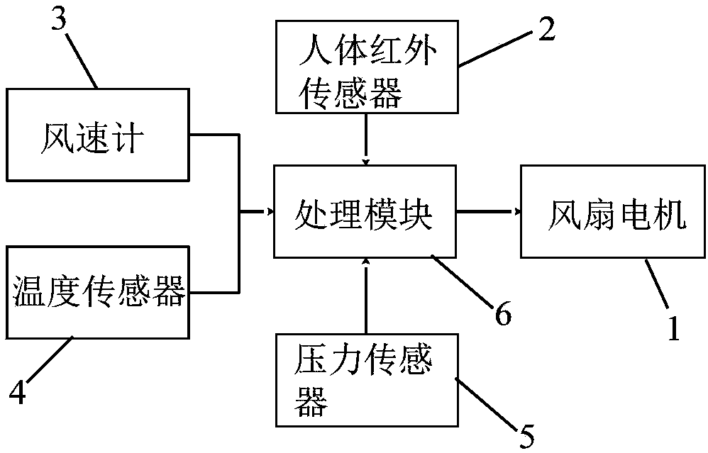
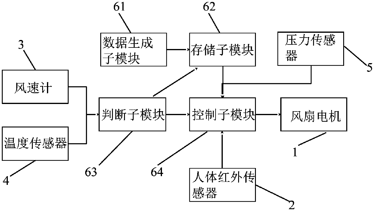
[0048] see figure 1 The present invention provides a fan safety and energy saving control system, which includes a fan body, a human body infrared sensor 2 , an anemometer 3 , a temperature sensor 4 , a pressure sensor 5 and a processing module 6 . Since the structure of the fan body in the present invention is the same as the structure of the existing fan, it will not be repeated here.

[0049]The human body infrared sensor 2 is used for detecting and judging whether there is human body infrared in the current environment, that is, when the human body infrared sensor 2 detects the existence of human body infrared, the human body infrared sensor will input a sensing signal to the processing module 6, The processing module 6 can determine that there is a human body in the current environment; when the human body infrared sensor 2 does not detect the existence of human body infrared, the human body infrared sensor does not input signals to the processing module 6, and the proces...


PUM


Abstract

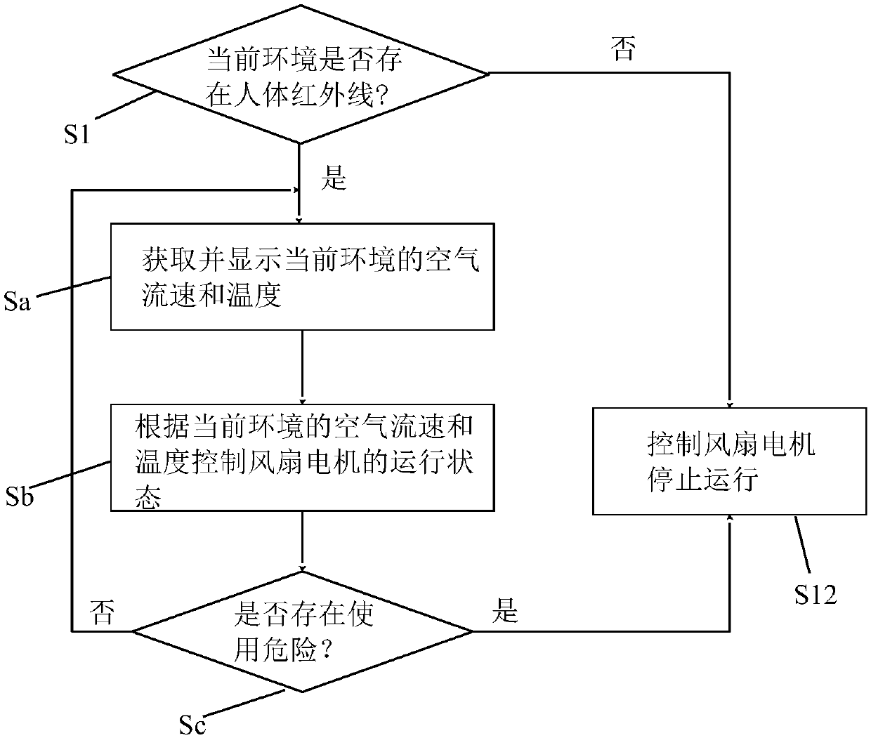
The invention relates to a fan safety and energy-saving control system. When a human body infrared sensor detects human body infrared rays and inputs a signal to a processing module, the processing module controls the pressure sensor, the anemometer and the temperature sensor to start running, and controls the fan according to the signals in the anemometer and the temperature sensor. The running speed and stop of the fan motor; during the start-up and operation of the fan motor, when the pressure sensor inputs a pressure signal to the processing module, the processing module controls the fan motor to stop running; when the human body infrared sensor cannot detect human infrared rays and no signal is input to the When processing the module, the processing module controls the pressure sensor, anemometer, temperature sensor, and fan motor to stop or remain inactive. Therefore, the working state of the fan motor is reasonably controlled through the human body infrared sensor, pressure sensor, air flow rate and temperature, so as to ensure the comfort of the user's environment, optimize the user experience, save energy and improve the safety of the fan.

Description

technical field [0001] The invention relates to the technical field of fan control, in particular to a fan safety and energy-saving control system. Background technique [0002] The fan is a device that generates airflow through electric drive. The motor configured in the fan drives the fan blades to rotate after being energized, and converts the electric energy into wind energy, so as to achieve the effect of generating wind and cooling. [0003] Existing fans generally have 3 control gears, which are respectively used to control the rotational speed of the motor to generate different wind speeds to meet the application in life or industry. During use, when the user feels that the current environment is stuffy, he will start the fan himself, and select the air volume blown by the fan through the control switch on the fan, thereby achieving the purpose of cooling. After using for a period of time, if the user feels discomfort caused by the current low ambient temperature, i...

Claims


Application Information

Patent Timeline
Patent Type & Authority Applications(China)
IPC IPC(8): F04D27/00
CPCF04D27/004F04D27/008
Inventor 王文杰
Owner 台山市合新压铸有限公司
Learn More