
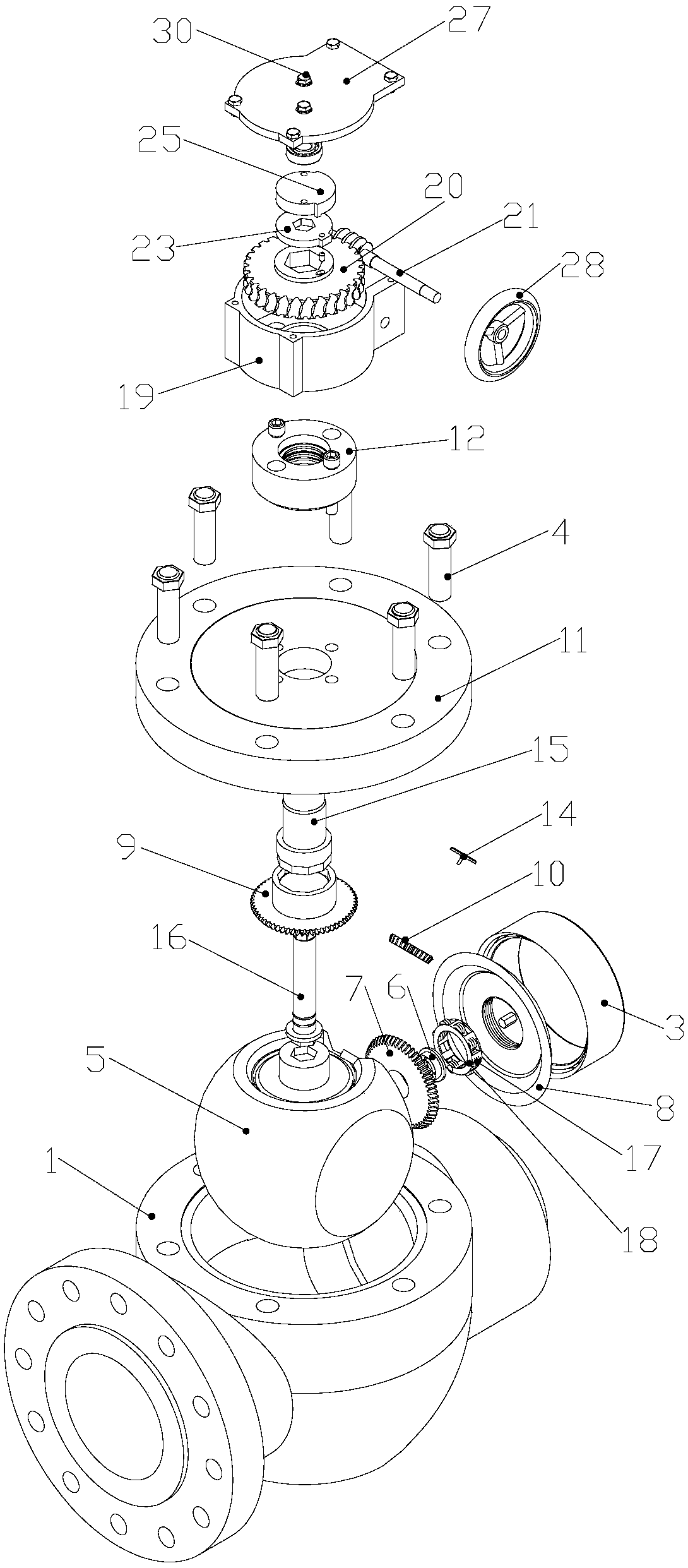
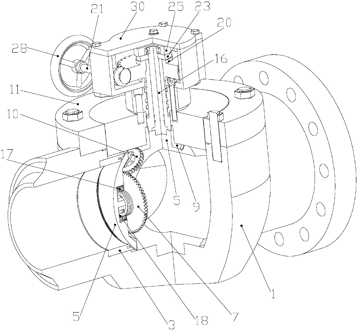
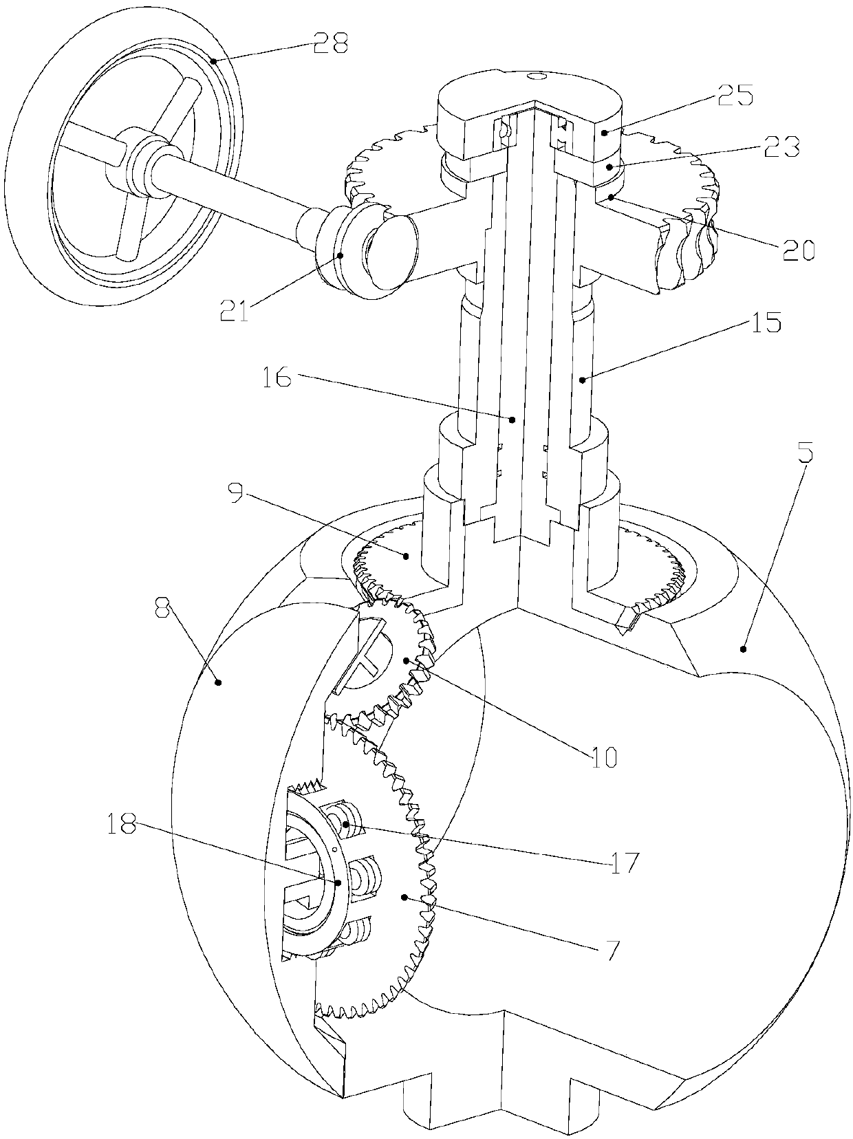
Forced sealing ball valve

A technology of forced sealing and ball valves, which is applied to valve details, valve devices, valve operation/release devices, etc., can solve problems such as unsatisfactory effects and large sliding friction, and achieve the effect of reducing friction and operating torque

Pending Publication Date: 2018-03-06
ZIBO VOTAISI PETROCHEM EQUIP CO LTD
View PDF7 Cites 14 Cited by
  • Summary
  • Abstract
  • Description
  • Claims
  • Application Information

AI Technical Summary

Problems solved by technology

However, the sliding friction between the threads in the screw fit is very large
Some friction can be reduced by using the necessary anti-friction materials, but the effect is not satisfactory

Method used


Image

  • Forced sealing ball valve
  • Forced sealing ball valve
  • Forced sealing ball valve

Examples


Embodiment Construction

[0050] In order to make the purpose, technical solutions and advantages of the embodiments of the present invention clearer, the technical solutions in the embodiments of the present invention will be clearly and completely described below in conjunction with the drawings in the embodiments of the present invention. Obviously, the described embodiments It is a part of embodiments of the present invention, but not all embodiments. The components of the embodiments of the invention generally described and illustrated in the figures herein may be arranged and designed in a variety of different configurations. Accordingly, the following detailed description of the embodiments of the invention provided in the accompanying drawings is not intended to limit the scope of the claimed invention, but merely represents selected embodiments of the invention. Based on the embodiments of the present invention, all other embodiments obtained by persons of ordinary skill in the art without cre...


PUM


Abstract

The invention relates to a forced sealing ball valve which comprises a valve body, a valve seat, a valve ball, a valve rod and a valve rod driving device, wherein the valve ball is arranged in the valve body. The valve rod is arranged on the valve ball, and the valve rod driving device is arranged at the upper end of the valve rod. The valve rod comprises an inner valve rod and an outer valve rod,and the valve ball comprises a valve ball base body, a valve clack and a gear transmission assembly, wherein the valve rod drives the valve ball to rotate in a reciprocating mode between an opening position and a closing position under the driving of the valve rod driving device, and the valve clack is jacked up from the valve body base body and is embraced with the valve seat when the valve ballbase body rotates to a closed position. The valve ball valve has the advantages of being simple to operate, safe, reliable and small in friction force.

Description

technical field [0001] The invention relates to a forced sealing ball valve. Background technique [0002] The traditional lifting rod type forced sealing ball valve, represented by the American ORBIT valve, adopts the design of the lifting valve stem track guide. Although the valve can realize no contact with the valve seat and no friction during most of the opening and closing process, the seal between the valve ball and the valve seat There is still relative sliding friction in the final engagement stage of the surface, and no frictionless rotation is truly achieved; the forced engagement between the valve ball and the valve seat can only be completed by pressing down the wedge surface of the valve stem and cooperating with the joint action of the lower pivot of the valve ball. Its action process is not stable enough, and it is easily affected by the relative position accuracy of the valve seat and pivot; the structure of the valve stem and its assembly is complex, and li...

Claims


Application Information

Patent Timeline
Patent Type & Authority Applications(China)
IPC IPC(8): F16K5/06F16K5/08F16K31/53F16K31/60
CPCF16K5/06F16K5/08F16K31/53F16K31/60
Inventor 毕作臣
Owner ZIBO VOTAISI PETROCHEM EQUIP CO LTD
Learn More