Cooling and heating unit

A refrigeration unit and unit technology, applied in refrigerators, refrigeration components, refrigeration and liquefaction, etc., can solve problems such as heat loss, inconvenient installation and transportation, environmental hazards, etc., and achieve the effects of prolonging service life, saving installation materials, and protecting the environment

Inactive Publication Date: 2018-03-06
CHENGDU JINCHUANTIAN AGRI MACHINE MFG
View PDF9 Cites 3 Cited by
  • Summary
  • Abstract
  • Description
  • Claims
  • Application Information

AI Technical Summary

Problems solved by technology

[0002] For a long time, the indoors are hotter in summer, and the outdoor temperature is higher when the windows are opened to ventilate. However, the use of air conditioners is very harmful to the environment. In winter, indoor heating is closed because the indoor air is not circulated, and the indoor air will become turbid over time. Opening doors and windows for ventilation will cause heat loss in the room
[0003] Most of the heating and cooling equipment on the market is realized by air conditioners, but a large amount of freon will be produced during the use of air conditioners, which will cause a lot of harm to the environment. Therefore, new heating and cooling equipment is needed
Heating Due to the problem of heating energy, some heating equipment is built on low floors, and consumes a lot of heat energy when heating high floors, and the cooling is provided through refrigerators, but the structure of refrigerators is complex and contains a large number of parts, which is extremely inconvenient for installation and transportation. The volume is large, and the parts cross each other during maintenance, which is not easy to maintain

Method used


Image

  • Cooling and heating unit
  • Cooling and heating unit
  • Cooling and heating unit

Examples


Embodiment

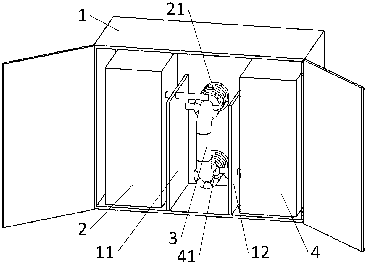
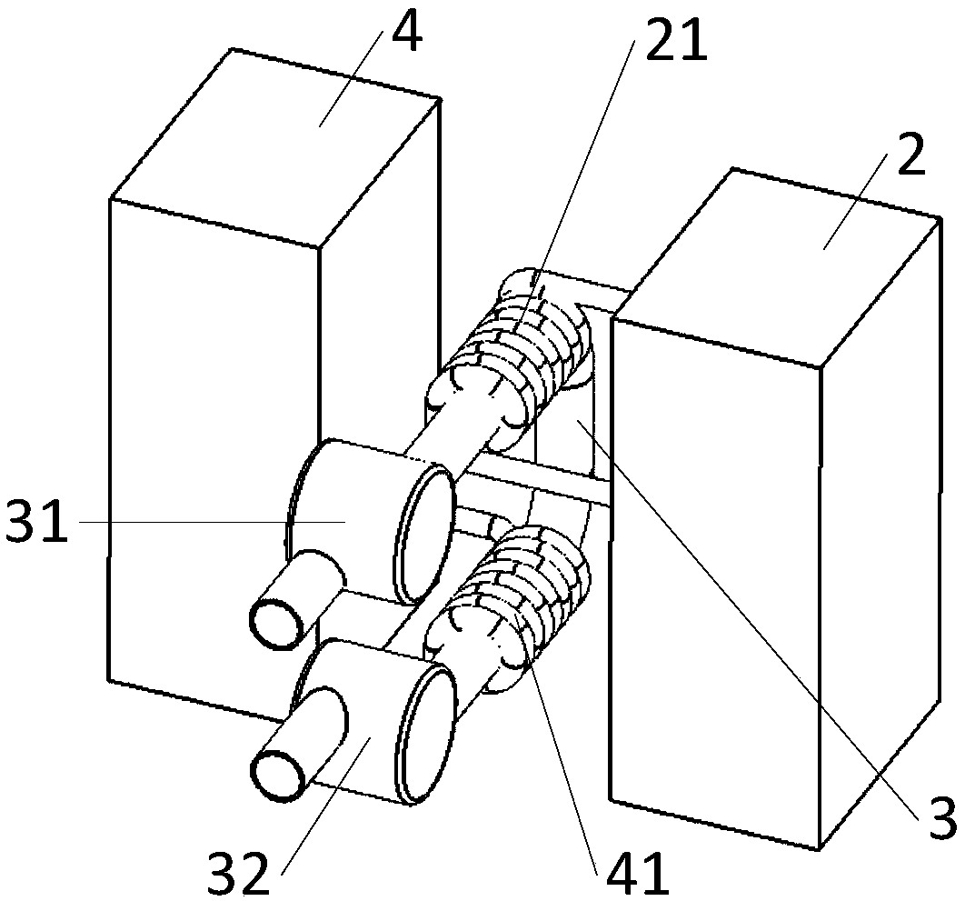
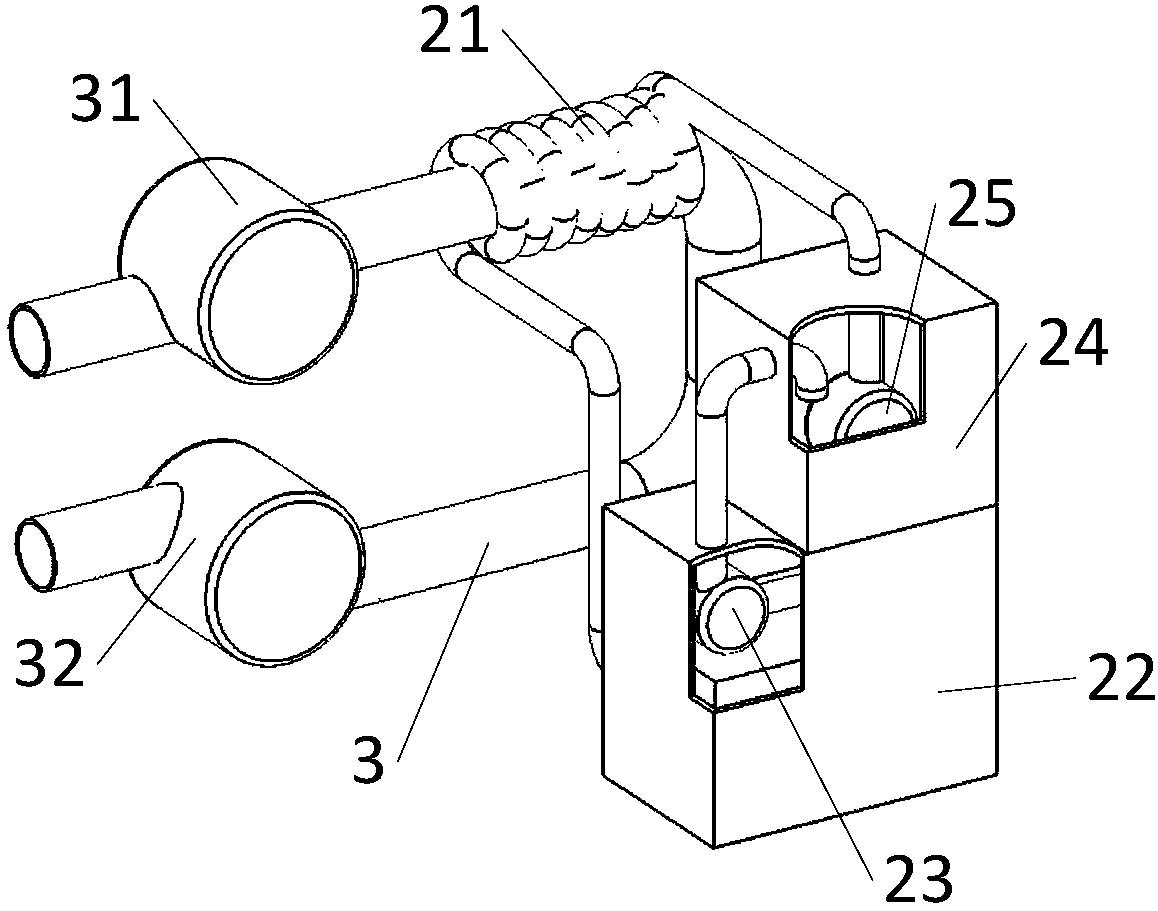
[0016] Such as Figure 1 ~ Figure 4 As shown, the cooling and heating unit provided in this embodiment includes a box body 1, a first partition 11, a second partition 12, a heater 22 group 2, a heating pipeline 21, an external pipeline 3, a hot water pump 31, a cold water pump 32, a cooling Unit 42 group 4, refrigeration pipeline 41, the first partition 11 and the second partition 12 arranged inside the box body 1 divide the box body 1 into three chambers, the external pipe 3 is arranged inside the middle chamber, and the heating machine 22 Group 2 and refrigerator 42 and group 4 are arranged inside the chambers on both sides, the external pipe 3 is U-shaped or C-shaped, and both ends of the external pipe 3 pass through the back of the box 1, and one port of the external pipe 3 is connected to the hot water pump 31 The other port of the external pipe 3 is connected to the cold water pump 32, and the heating pipe 21 of the heating machine 22 group 2 and the cooling pipe 41 of t...


PUM


Abstract

The invention discloses a cooling and heating unit. A first partition plate and a second partition plate which are arranged in a box body divide the box body into three cavities, wherein an external pipeline is arranged in a middle cavity, and a heating unit and a cooling unit are arranged in the cavities at the two sides respectively; the external pipeline is U-shaped or C-shaped, and the two ends of the external pipeline penetrate through the back surface of the box body; one end of the external pipeline is connected with a hot water pump, and the other end of the external pipeline is connected with a cold water pump; and a heating pipeline of the heating unit and a cooling pipeline of the cooling unit are both arranged on the external pipeline in a surrounding mode. The cooling and heating unit adopts an integrated module design, so that replacement and maintenance are convenient; the heating unit and the cooling unit are effectively combined with the external pipeline, and therefore heating and cooling can be realized through the same channel, additional installation materials are saved, and meanwhile, the environment is protected; and the flow directions of the hot water pumpand the cold water pump are different, so that heating and cooling are not carried out at the same time, and the service life of the external pipeline is prolonged.

Description

technical field [0001] The invention relates to the field of heating equipment, in particular to a cooling and heating unit. Background technique [0002] For a long time, the indoors are hotter in summer, and the outdoor temperature is higher when the windows are opened to ventilate. However, the use of air conditioners is very harmful to the environment. In winter, indoor heating is closed because the indoor air is not circulated, and the indoor air will become turbid over time. Opening doors and windows for ventilation will cause heat loss in the room. [0003] Most of the cooling and heating equipment on the market is realized by air conditioners, but a large amount of freon will be produced during the use of air conditioners, which will cause a lot of harm to the environment. Therefore, new heating and cooling equipment is needed. Heating Due to the problem of heating energy, some heating equipment is built on low floors, and consumes a lot of heat energy when heating ...

Claims


Application Information

Patent Timeline
IPC IPC(8): F25B30/02
CPCF25B30/02
Inventor 张钉
Owner CHENGDU JINCHUANTIAN AGRI MACHINE MFG
Why Eureka
Try Eureka