Ultrasonic pipe flaw detection device

A flaw detection device, ultrasonic technology, used in measuring devices, material analysis using sound waves/ultrasonic waves/infrasonic waves, cleaning hollow objects, etc.

Inactive Publication Date: 2018-03-06
宋欢
View PDF0 Cites 12 Cited by
  • Summary
  • Abstract
  • Description
  • Claims
  • Application Information

AI Technical Summary

Problems solved by technology

In addition, the device proposed by the present invention can realize automatic switching between the liquid-filled pipeline and the empty...

Method used


Image

  • Ultrasonic pipe flaw detection device
  • Ultrasonic pipe flaw detection device
  • Ultrasonic pipe flaw detection device

Examples


Embodiment Construction

[0028] In order to make the content of the present invention easier to be understood clearly, the following further describes the present invention in detail based on specific embodiments in conjunction with the accompanying drawings.

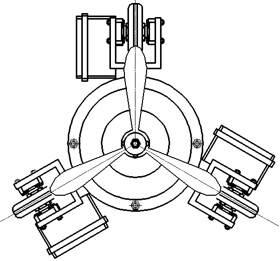
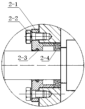
[0029] Such as Figure 1~3 As shown, an ultrasonic pipeline flaw detection device includes a drive impeller 1, an impeller drive shaft 3, a drive wheel set 13, a driven wheel set 4, an impeller drive coupling 6, an impeller drive DC motor 7, a fastening screw 2, an impeller drive battery 8. Steel brush drive DC motor 9, steel brush 16, ultrasonic detection component 14, rubber bellows 5, steel brush drive shaft 15, steel brush drive shaft coupling 11, steel brush drive battery 10, and body 12. The fuselage 12 serves as a base to fix and connect the main components. The impeller 1 is driven by the impeller-driven DC motor 6 through the coupling 6 to drive the impeller drive shaft 3. The impeller-driven DC motor 7 is fixed on the support plate of th...


PUM

PropertyMeasurementUnit
Thicknessaaaaaaaaaa

Abstract

The invention discloses an ultrasonic pipeline flaw detection device, which has the function of completing flaw detection tasks for buried and underwater concealed pipelines, and can realize automatic turning especially for long-distance transmission pipelines, and can remove dirt on the inner wall of the pipeline to realize accurate flaw detection. At the same time, the device proposed by the invention can simultaneously realize efficient flaw detection in the liquid-filled pipeline and the empty pipeline, and solve the technical problem that the prior art cannot work uninterruptedly under variable working conditions.

Description

Technical field [0001] The invention relates to a flaw detection device, in particular to an ultrasonic flaw detection device for a concealed pipeline. Background technique [0002] Under the effects of long-term oxidation, gas / liquid pressure, impurity impact, etc., buried or underwater oil pipelines and gas pipelines will cause damage to the inner surface of the pipeline and cracks inside, which may cause safety hazards. At present, there are many pipeline flaw detection technologies, mainly including ultrasonic testing, eddy current testing, magnetic particle testing, radiographic testing, penetrant testing, visual testing, infrared testing, microwave testing and so on. In contrast, ultrasonic monitoring technology is relatively mature, with the advantages of high data resolution, low monitoring cost, and simple structure. Ultrasonic flaw detection is a method that uses ultrasonic energy to penetrate deep into the metal material, and when one section enters another section, r...

Claims


Application Information

Patent Timeline
IPC IPC(8): G01N29/22G01N29/265B08B9/051
CPCG01N29/22B08B9/051G01N29/225G01N29/265G01N2291/023G01N2291/0289
Inventor 宋欢
Owner 宋欢
Why Eureka
Try Eureka