Laser scanning device and mobile measurement system

A laser scanning device and laser technology, applied in the field of laser scanning, can solve the problems of restricting the use environment of the system and not being able to scan areas in three-dimensional space

Inactive Publication Date: 2018-03-06
WUHAN HI TARGET DIGITAL CLOUD TECH CO LTD
View PDF8 Cites 11 Cited by
  • Summary
  • Abstract
  • Description
  • Claims
  • Application Information

AI Technical Summary

Problems solved by technology

[0002] Existing laser scanning devices cannot scan the entire three-dimensional space because they can only scan the target area of ​​a planar area
When applied to the construction system of the 3D digital model, it is necessary to combine the global satellite navigation system (GNSS) and the inertial measurement unit (IMU) for integration and data fusion, and the global satellite navigation system (GNSS) has the limitation of signal factors, which limits the The environment in which the system is used

Method used


Image

  • Laser scanning device and mobile measurement system
  • Laser scanning device and mobile measurement system
  • Laser scanning device and mobile measurement system

Examples


no. 1 example

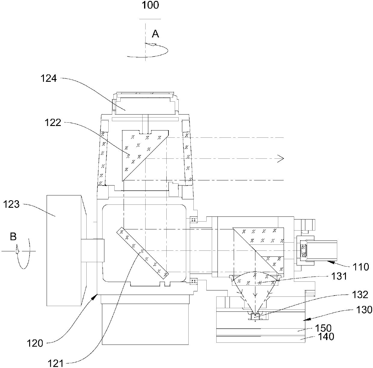
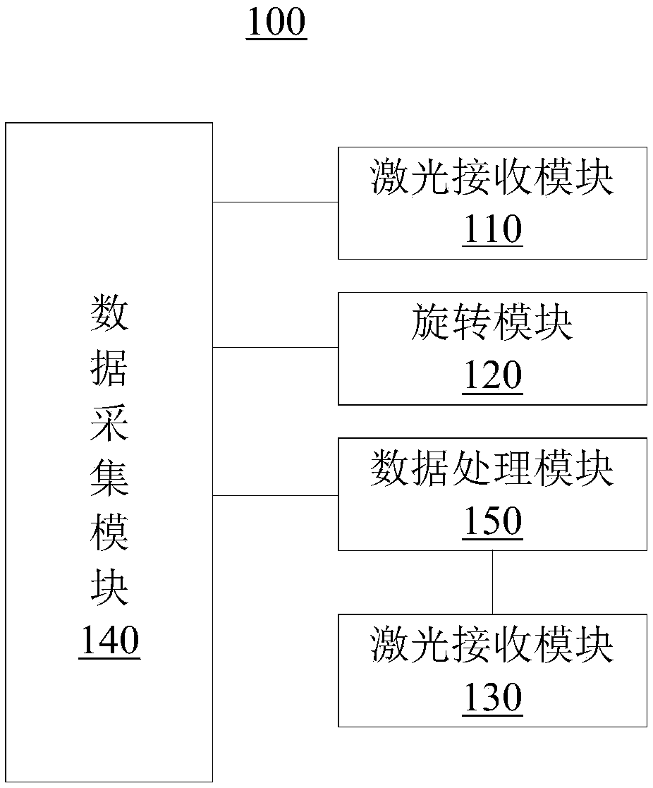
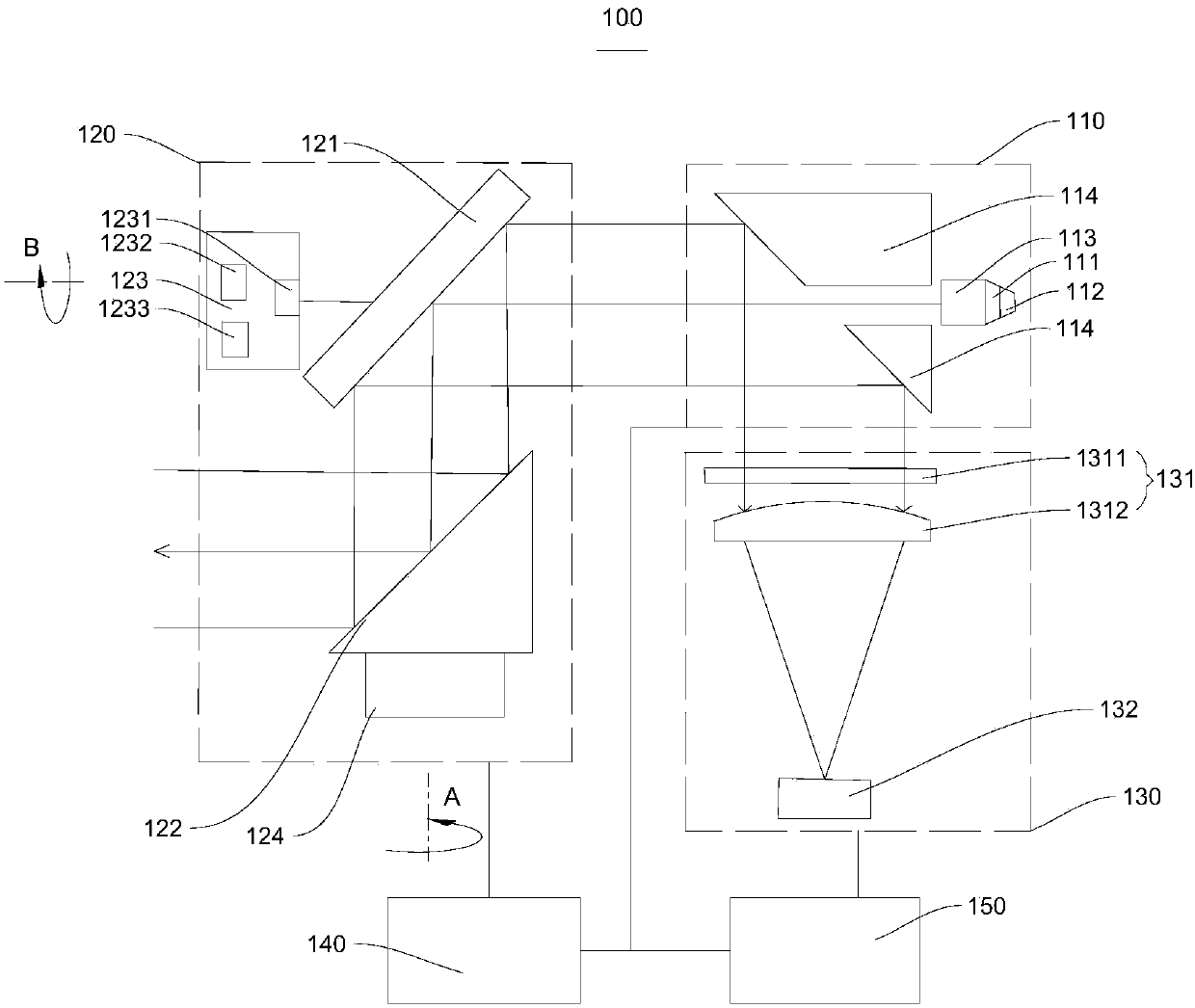
[0026] The embodiment of the present invention provides a laser scanning device 100, please refer to figure 1 , the laser scanning device 100 includes a laser emitting module 110 , a rotating module 120 , a laser receiving module 130 , a data collecting module 140 and a data processing module 150 . Wherein, the laser emitting module 110 and the laser receiving module 130 are disposed on one side of the rotating module 120 . The laser emitting module 110 is used to emit laser light, and the rotating module 120 is used to change the direction of the laser light so that the laser light can be irradiated to targets in various positions of the target scene. The laser receiving module 130 is used for receiving the laser light reflected by the target and performing photoelectric conversion to obtain an electrical signal. The data processing module 150 is used to process the electrical signal to obtain the time difference between the laser light emitted by the laser emitting module 1...

no. 2 example

[0048] The second embodiment of the present invention provides a mobile measurement system 200, please refer to Figure 5 , the mobile measurement system 200 includes a processing device 210, an inertial measurement device 230, and the laser scanning device 100 provided in the first embodiment of the present invention. Wherein, the processing device 210 is respectively connected with the laser scanning device 100 and the inertial measurement device 230 , and the specific connection manner may be electrical connection. The inertial measurement device 230 is used to acquire the motion data of the mobile measurement system 200, and the processing device 210 is used to collect the point cloud of the target scene collected by the data acquisition module of the laser scanning device 100 based on a preset slam algorithm The data and the motion data obtained by the inertial measurement device 230 are processed to obtain a three-dimensional image of the target scene. Therefore, the sl...


PUM


Abstract

The embodiment of the invention provides a laser scanning device and a mobile measurement system, and relates to the technical field of laser scanning. The laser scanning device comprises a laser transmitting module, a rotating module, a laser receiving module, a data acquisition module and a data processing module, wherein the laser transmitting module and the laser receiving module are arrangedat one side of the rotating module, the rotating module is used for changing the direction of laser light so as to enable the laser light to irradiate to target objects at each position of a target scene, the laser receiving module is used for receiving the laser light reflected by the target objects and performing photoelectric conversion to obtain an electric signal, the data processing module is used for processing the electric signal to obtain the time difference between the transmitted laser light and the received laser light, and the data acquisition module is used for acquiring data ofthe laser transmitting module, the rotating module and the data processing module so as to obtain point cloud data of the target scene. The laser scanning device can acquire three-dimensional data ofa three-dimensional space of the target scene. In addition, the device can perform mobile measurement under a condition that GNSS signals are unavailable.

Description

technical field [0001] The invention relates to the technical field of laser scanning, in particular to a laser scanning device and a mobile measuring system. Background technique [0002] Existing laser scanning devices cannot scan the entire three-dimensional space because they can only scan a target area in a planar area. When applied to the construction system of the 3D digital model, it is necessary to combine the global satellite navigation system (GNSS) and the inertial measurement unit (IMU) for integration and data fusion, and the global satellite navigation system (GNSS) has the limitation of signal factors, which limits the The environment in which the system is used. Contents of the invention [0003] In view of this, the present invention provides a laser scanning device and a mobile measurement system to improve the above problems. [0004] To achieve the above object, the present invention provides the following technical solutions: [0005] A laser scann...

Claims


Application Information

Patent Timeline
Patent Type & Authority Applications(China)
IPC IPC(8): G01S17/89G01S7/481G02B26/10
CPCG02B26/105G01S7/4816G01S7/4817G01S17/89
Inventor 刘守军杨正肖亮胡庆武翁国康
Owner WUHAN HI TARGET DIGITAL CLOUD TECH CO LTD
Why Eureka
Try Eureka