
Light emitting device and manufacturing method thereof

A technology of light-emitting devices and light-emitting elements, which is applied in the direction of electrical components, circuits, semiconductor devices, etc., and can solve problems such as uneven distribution of mixed light color or color temperature

Inactive Publication Date: 2018-03-06
EPISTAR CORP
View PDF6 Cites 1 Cited by
  • Summary
  • Abstract
  • Description
  • Claims
  • Application Information

AI Technical Summary

Problems solved by technology

[0006] In addition, under the trend of shrinking LED size after packaging, the light mixing distance between LED and wavelength conversion material becomes smaller, so it is easy to cause the problem of uneven distribution of color or color temperature of mixed light

Method used


Image

  • Light emitting device and manufacturing method thereof
  • Light emitting device and manufacturing method thereof
  • Light emitting device and manufacturing method thereof

Examples


Embodiment Construction

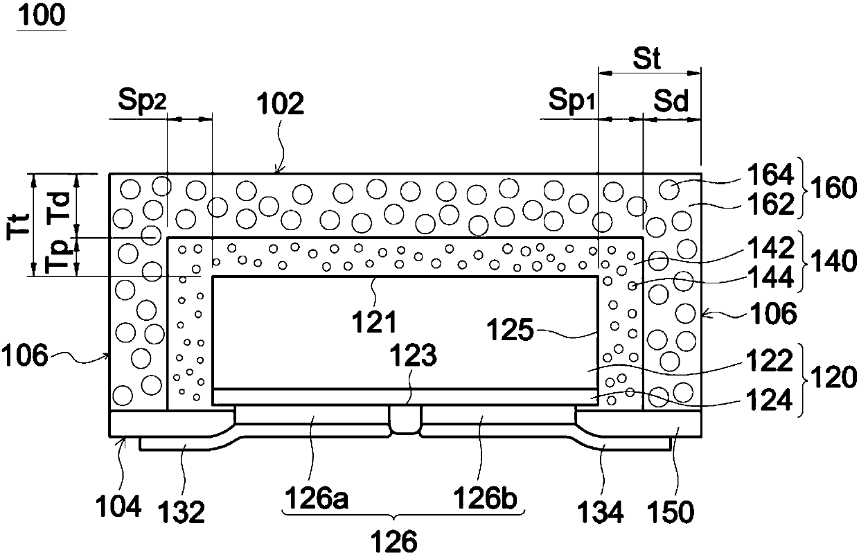
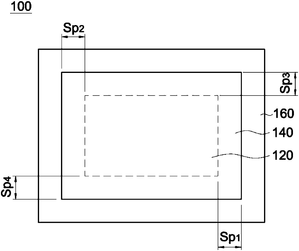
[0066] Herein, the light-emitting device includes at least one light-emitting element, and the light-emitting device has one or more total side thicknesses S t , where the total side thickness S t It refers to the distance between the side of the light-emitting device and the side of the light-emitting element. Total top thickness T t refers to the distance between the top surface of the light emitting device and the upper surface of the light emitting element. For the types or configurations of the side and top surfaces of the light emitting device or the side and top surfaces of the light emitting element, please refer to the descriptions of the various embodiments below.

[0067] Figure 1AIt is a cross-sectional view of a light emitting device 100 disclosed according to an embodiment of the present invention. The light emitting device 100 includes a light emitting element 120 , a wavelength conversion layer 140 and a light adjustment layer 160 . The wavelength conversi...


PUM


Abstract

The invention provides a light emitting device and a manufacturing method thereof. The light emitting device comprises a light emitting element, a wavelength conversion layer and a light adjusting layer. The light emitting element comprises a first upper surface, a lower surface and a side surface between the first upper surface and the lower surface. The wavelength conversion layer comprises a transparent adhesive, multiple wavelength conversion particles and a second upper surface which covers the first upper surface. The light adjusting layer surrounds the side surface of the light emittingelement and has a first composition or a second composition. The first composition comprises a first adhesive and multiple first diffusion particles which are dispersed in the first adhesive. The weight percentage between the multiple first diffusion particles and the light adjusting layer is not smaller than 20%. The second composition comprises a second adhesive, multiple second diffusion particles which are dispersed in the second adhesive, and multiple light diffusion particles which are dispersed in the second adhesive. The weight percentage between the multiple second diffusion particles and the light adjusting layer is not lower than 5%. Furthermore the weight percentage between the multiple light diffusion particles and the light adjusting layer is not lower than 0.4%.

Description

technical field [0001] The present invention relates to a light emitting device and a manufacturing method thereof, in particular to a light emitting device including a wavelength conversion layer and a light adjustment layer and a manufacturing method thereof. Background technique [0002] The light-emitting diode element (Light-Emitting Diode; LED) in the solid-state light-emitting element has the characteristics of low power consumption, low heat generation, long operating life, impact resistance, small size, and fast response, so it is widely used in various needs. The field of light-emitting elements, for example, vehicles, home appliances, and lighting fixtures. [0003] There are several ways to convert the pure color light emitted by LEDs into light of other colors. For example, the LED can be covered with a wavelength conversion layer, such as a phosphor layer, to achieve this purpose. Phosphor powder is a photoluminescent substance, which can also be said to be a...

Claims


Application Information

Patent Timeline
IPC IPC(8): H01L33/50H01L33/58
CPCH01L33/505H01L33/58H01L2933/0091
Inventor 郑景太赖隆宽郭儒莲石俊华彭宣慈任益华
Owner EPISTAR CORP
Learn More