High-conduction grid structure of lead acid storage battery and processing method of high-conduction grid structure

A lead-acid battery and processing method technology, applied in the direction of electrode carrier/current collector, etc., can solve the problems of inability to be popularized, high copper price, complicated process, etc., to ensure charging acceptance and cycle life, reduce costs, and improve current. The effect of distribution uniformity

Active Publication Date: 2018-03-06
CHAOWEI POWER CO LTD
View PDF6 Cites 3 Cited by
  • Summary
  • Abstract
  • Description
  • Claims
  • Application Information

AI Technical Summary

Problems solved by technology

However, the price of copper is high, and it needs to be electroplated with lead alloy. The process is complicated and the cost is high. It cannot be popularized in other fields and small-scale lead-acid batteries.

Method used


Image

  • High-conduction grid structure of lead acid storage battery and processing method of high-conduction grid structure
  • High-conduction grid structure of lead acid storage battery and processing method of high-conduction grid structure

Examples


Embodiment 1

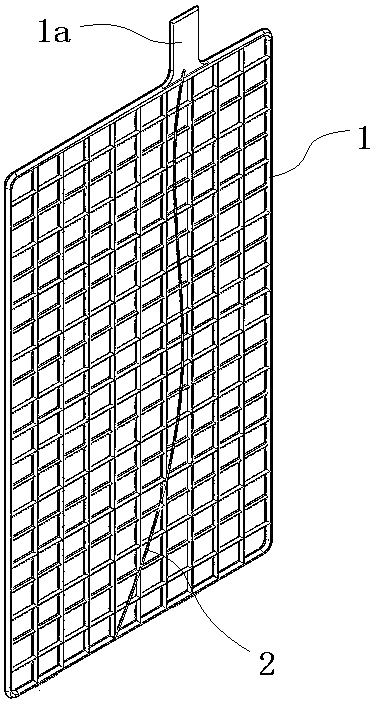
[0024] Such as figure 1 In the illustrated embodiment, a high-conductivity grid structure for a lead-acid battery includes a grid 1 in a grid state. One side of the grid is provided with tabs 1a, which protrude from the edge of the grid and are used to connect with external wires. At least one highly conductive rib 2 is provided on the grid, and the highly conductive rib is made of highly conductive metal or non-metal and composite materials. Highly conductive ribs are made of highly conductive metals or non-metals and composite materials. Highly conductive metals can be copper, copper alloys, aluminum, aluminum alloys and other metal materials. Non-metals include graphite, conductive polymers, etc., and composite materials include graphite. vinyl composite materials and other materials. One end of the highly conductive rib is fixedly connected to the tab, and the other end of the high conductive rib is fixedly connected to one side of the grid. Highly conductive ribs can b...

Embodiment 2

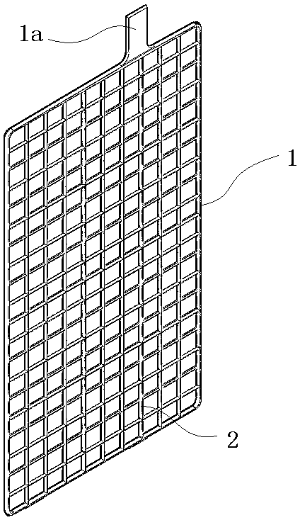
[0031] Such as figure 2 In the illustrated embodiment, a high-conductivity grid structure for a lead-acid battery includes a grid 1 in a grid state. One side of the grid is provided with tabs 1a, which protrude from the edge of the grid and are used to connect with external wires. At least one highly conductive rib 2 is arranged on the grid, and the highly conductive rib is made of highly conductive metal or non-metal and composite materials. Highly conductive ribs are made of highly conductive metals or non-metals and composite materials. Highly conductive metals can be copper, copper alloys, aluminum, aluminum alloys and other metal materials. Non-metals include graphite, conductive polymers, etc., and composite materials include graphite. vinyl composite materials and other materials. One end of the highly conductive rib is fixedly connected to the tab, and the other end of the high conductive rib is fixedly connected to one side of the grid. The highly conductive ribs ...


PUM


Abstract

The invention discloses a high-conduction grid structure of a lead acid storage battery and a processing method of the high-conduction grid structure. The grid structure comprises a grid, wherein a tab is arranged at one side of the grid, at least one high-conduction rib is arranged on the grid, one end of the high-conduction rib is fixedly connected with the tab, and the other end of the high-conduction rib is fixedly connected with a side edge of the grid. The processing method comprises the following steps of (a) covering an acid corrosion-resistant material on a surface of the high-conduction rib, and cutting the high-conduction rib after being covered with the acid corrosion-resistant material to segments; (b) fixing the high-conduction rib which is cut to segments and the grid; and (c) detecting the high-conduction rib and the grid which are fixed so that the high-conduction rib and the grid are enabled to be in a conduction state. The invention aims to provide the high-conduction grid structure of the lead acid storage battery and the processing method of the high-conduction grid structure, which can be used for improving the electrical conducted of the grid and current uniformity during the charge-discharge process.

Description

technical field [0001] The invention belongs to the field of storage battery manufacturing, and in particular relates to a high-conductivity grid structure and a processing method of a lead-acid storage battery. Background technique [0002] At present, the battery is equipped with a grid as an electrode. The grid is used as the skeleton of the active material to support the active material; the second is used as a conductive network to input and output electric energy from the active material. Traditional lead-acid battery grids are made of lead alloys, which have higher resistivity and lower strength, and the amount of lead material used in the grid is larger. The main failure modes of the battery are as follows: first, a non-conductive layer appears at the interface between the battery grid and the active material, resulting in a rapid decline in the early capacity of the battery; second, the softening and falling off of the positive active material; third, "irreversible ...

Claims


Application Information

Patent Timeline
Patent Type & Authority Applications(China)
IPC IPC(8): H01M4/73H01M4/82
CPCY02E60/10
Inventor 刘孝伟章晖
Owner CHAOWEI POWER CO LTD
Why Eureka
Try Eureka