
A space-borne fixed surface deployable antenna

A spaceborne and antenna technology, applied in the field of spaceborne fixed surface deployable antennas, can solve the problems of low reflector accuracy, low deployment accuracy, small deployment aperture, etc., and achieves broad application prospects, no moving singular points, and high deployment accuracy. Effect

Inactive Publication Date: 2020-04-03
NORTHWESTERN POLYTECHNICAL UNIV
View PDF8 Cites 0 Cited by
  • Summary
  • Abstract
  • Description
  • Claims
  • Application Information

AI Technical Summary

Problems solved by technology

Existing antennas of this type generally have defects such as small deployment aperture, low deployment accuracy, poor support stiffness, low reflection surface precision, and sensitive impact response, which directly affect the service life and performance of satellites, making it difficult to meet the needs of large-scale spaceborne antenna systems. needs
[0004] Invention patent CN 105896020 A discloses "an expandable solid-surface antenna". The fixed-surface antenna is characterized by high storage rate and high precision of the reflective surface, but the expansion aperture is limited due to its own structure, and cannot be applied to large-scale expandable antennas. , and the support stiffness and deployment accuracy are poor, it is difficult to ensure that each panel of the antenna can be deployed smoothly
[0005] Invention patent CN 103872422 A proposes "an umbrella-shaped expandable antenna system". The antenna system has a high storage rate and light weight, but the expansion aperture is small, which is suitable for small expandable antennas; when the expansion aperture increases, the antenna The deployment process of the reflector is quite difficult in actual operation; in the harsh high and low temperature environment in space, the profile of the antenna reflector is prone to change, the stability of the profile system is not high, and it does not have a high profile. Surface accuracy and surface retention ability, which in turn affects the performance of the antenna reflector

Method used


Image

  • A space-borne fixed surface deployable antenna
  • A space-borne fixed surface deployable antenna
  • A space-borne fixed surface deployable antenna

Examples


Embodiment Construction

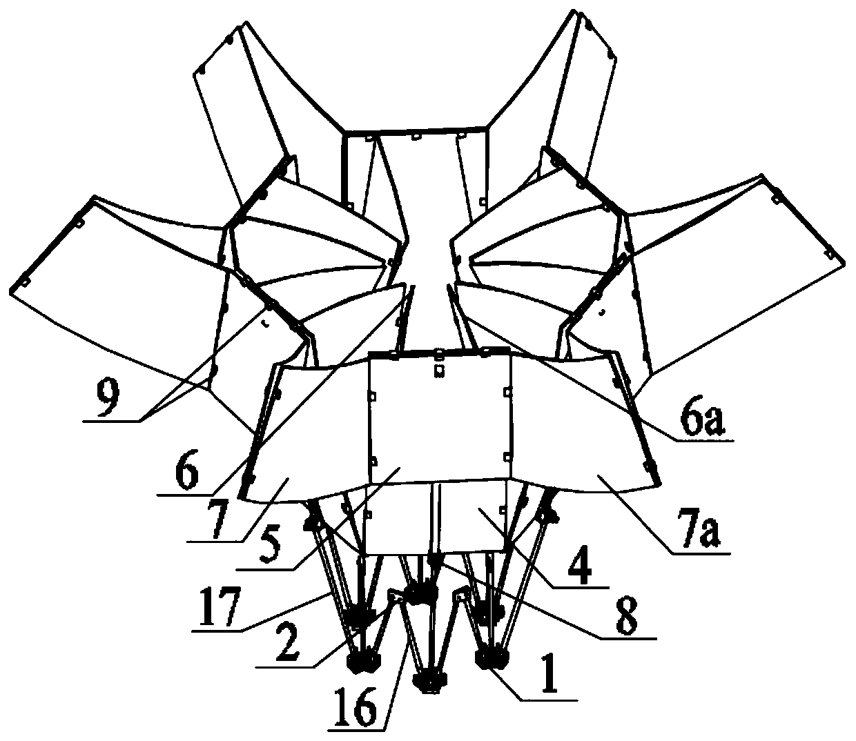
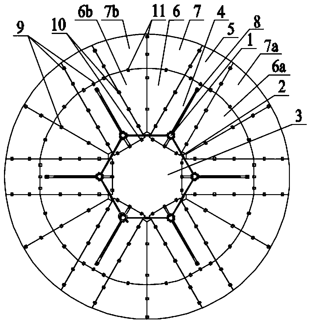
[0044] This embodiment is a space-borne fixed surface deployable antenna.

[0045] refer to Figure 1 to Figure 15 In this embodiment, the space-borne fixed-surface deployable antenna has a deployment diameter of 12m; it includes a fixed-surface reflector 35 composed of a plurality of rigid thin plates, and a deployable mechanism 34 for supporting and controlling the deployment of the fixed-surface antenna and the switching of the folded state. and drive components for power units. The drive assembly includes a drive motor 36 and an elastic energy storage element 9; the solid surface reflector 35 is connected to the expandable mechanism 34 through a universal hinge 8, and the drive motor 36 is connected to the synchronous three-bar expandable unit 1; the electrical signal and the drive assembly Under the action, the fixed surface reflector 35 realizes secondary spatial expansion from the initial folded state through the expandable mechanism 34 and the elastic energy storage e...


PUM


Abstract

The invention discloses a satellite-borne solid-surface deployable antenna which is composed of a solid-surface reflector, a deployable mechanism and a driving component. The deployable mechanism is composed of multiple synchronous three-bar deployable units and synchronous two-bar deployable units combined in an array. The solid-surface reflector is composed of a plurality of rigid sheets. The driving component includes a driving motor and an elastic energy storage element. The solid-surface reflector and the deployable mechanism are connected through a universal hinge. Under the action of the driving motor, the solid-surface reflector realizes first spatial synchronous deployment through the deployable mechanism. Under the action of the elastic energy storage element and a compression spring, the solid-surface reflector realizes second spatial synchronous deployment. After deployment, any two adjacent panels of the solid-surface reflector are hinged and locked by a locking mechanism,and the whole antenna is stabilized in a fully deployed state. The satellite-borne solid-surface deployable antenna has the characteristics of large deployment aperture, high deployment and support stiffness, and high precision of surface profile, and can be used as a reflector or a collector in space or on the ground.

Description

technical field [0001] The invention relates to the technical field of satellite antenna structure design, in particular to a space-borne fixed surface deployable antenna. Background technique [0002] Antenna, as a kind of wireless communication equipment, plays a huge role in many fields such as aerospace, meteorology, communication and military affairs. At present, space-borne antennas are widely used in various satellite systems. With the continuous development of aerospace technology and the continuous expansion of aerospace applications, it has become a development trend to develop large-aperture, high-precision, and light-weight space-borne antennas. However, due to the limitation of the effective accommodation space and carrying capacity of the launch vehicle, the antenna is required to be fixed in the payload compartment of the vehicle in a retracted state during the launch phase. Complete the unfolding process step by step, then lock it and keep it in the working ...

Claims


Application Information

Patent Timeline
Patent Type & Authority Patents(China)
IPC IPC(8): H01Q1/08H01Q15/16
CPCH01Q1/08H01Q15/162
Inventor 王三民卢江昇高举姚亮余澍民李浩
Owner NORTHWESTERN POLYTECHNICAL UNIV
Learn More