Improved pulper vertical pipe
A refiner and standpipe technology, applied in pulp beating/refining method, textile and papermaking, fiber raw material processing, etc., can solve problems such as clogging equipment, large temperature difference between inside and outside refiner standpipe, affecting papermaking process, etc.
- Summary
- Abstract
- Description
- Claims
- Application Information
AI Technical Summary
Problems solved by technology
Method used
Image
Examples
Embodiment 1
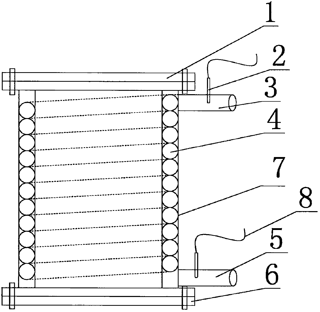
[0012] Such as figure 1 As shown, this embodiment provides an improved refiner standpipe, including a hollow cylindrical standpipe body 7, the upper end of the standpipe body 7 is connected with an upper flange 1 connected to the refiner, and the riser pipe The lower end of the body 7 is connected with the lower flange 6 connected with the screw feeder, the joints of the upper flange 1 and the lower flange 6 and the standpipe body 7 are provided with gaskets, and the riser body 7 The inner wall is provided with an interlayer, and in the interlayer is provided a spirally arranged hot water pipe 4 for passing in hot water. The upper and lower ends of the hot water pipe 4 are respectively provided with a water inlet 3 and a water outlet 5. 80 degrees Celsius Hot water enters from the water inlet 3 and is discharged from the water outlet 5, which effectively ensures that there is no temperature difference between the inside and outside of the standpipe of the refiner.
Embodiment 2
[0014] This embodiment provides an improved standpipe of a refiner, including a hollow cylindrical standpipe body 7, the upper end of the standpipe body 7 is connected with an upper flange 1 connected to the refiner, and the lower end of the standpipe body 7 is The lower flange 6 connected with the screw feeder is connected, and the joints between the upper flange 1 and the lower flange 6 and the standpipe body 7 are provided with gaskets, and the inner wall of the standpipe body 7 is provided with The interlayer is provided with a spirally arranged hot water pipe 4 inside the interlayer for passing in hot water. The upper and lower ends of the hot water pipe 4 are respectively provided with a water inlet 3 and a water outlet 5 . The position of the water inlet 3 is provided with a first temperature sensor 2 for online measurement of the temperature of the water inlet.
Embodiment 3
[0016] This embodiment provides an improved standpipe of a refiner, including a hollow cylindrical standpipe body 7, the upper end of the standpipe body 7 is connected with an upper flange 1 connected to the refiner, and the lower end of the standpipe body 7 is The lower flange 6 connected with the screw feeder is connected, and the joints of the upper flange 1 and the lower flange 6 and the standpipe body 7 are provided with sealing gaskets, and the inner wall of the standpipe body 7 is provided with The interlayer is provided with a spirally arranged hot water pipe 4 inside the interlayer for passing in hot water. The upper and lower ends of the hot water pipe 4 are respectively provided with a water inlet 3 and a water outlet 5 . The position of the water outlet 5 is provided with a second temperature sensor 8 for online measurement of the temperature of the water outlet.
PUM
 Abstract
Description
Claims
Application Information
 - R&D
- Intellectual Property
- Life Sciences
- Materials
- Tech Scout
- Unparalleled Data Quality
- Higher Quality Content
- 60% Fewer Hallucinations
Browse by: Latest US Patents, China's latest patents, Technical Efficacy Thesaurus, Application Domain, Technology Topic, Popular Technical Reports.
© 2025 PatSnap. All rights reserved.Legal|Privacy policy|Modern Slavery Act Transparency Statement|Sitemap|About US| Contact US: help@patsnap.com

